
Component Encyclopedia

What is it? How do I connect it? What can I build? Every part explained simply.

44Components 11Categories 3.3 VESP32 focus
ESP32 components and classroom electronics kits on desks

44 components

Product-style illustration of 13.56 MHz RFID Key Fob; not a verified physical pin layout
Communication ModulesBeginner

13.56 MHz RFID Key Fob: Reader Compatibility

Pair a documented passive MIFARE Classic-family fob with a compatible reader. A UID demonstration is not secure access control.
Communication ModulesSupply: Passive tag energized by compatible reader field; no wired supply.Signal: No fob-to-GPIO signal. The separate MFRC522 reference reader uses3.3 V supply/SPI logic.Protection: Follow the reader power/pinout circuit. Do not connect USB/5 V or probe wires to the fob.
View Guide
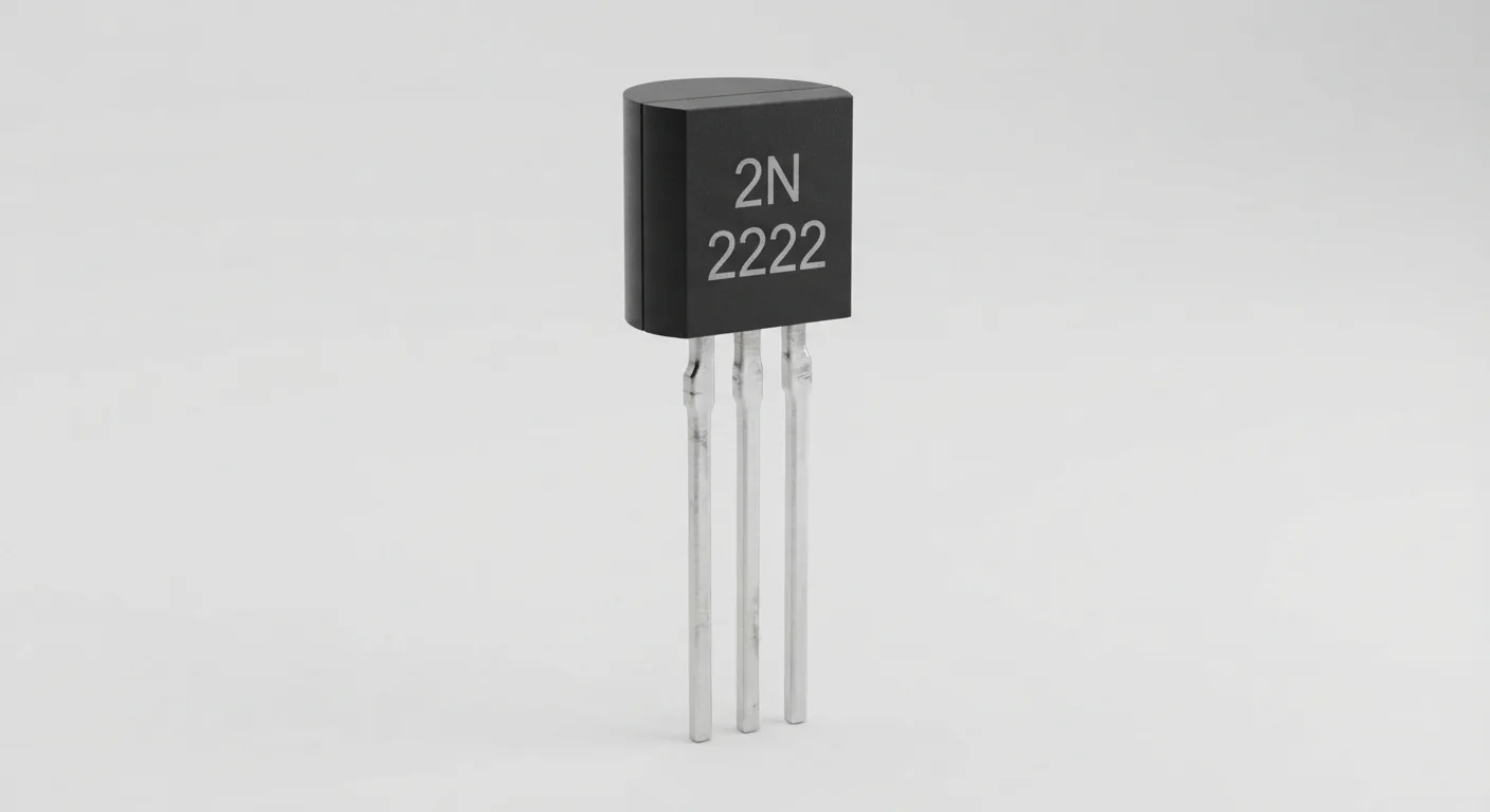
Product-style illustration of 2N2222 NPN Transistor; not a verified physical pin layout
Power ComponentsBeginner

2N2222 NPN Transistor: Switch a Small LED with ESP32

Learn base, collector and emitter connections using a documented P2N2222A and a small 3.3 V LED load. A base resistor and verified package pinout are essential.
Power ComponentsSupply: 3.3 V LED supply in this example; emitter at common GND.Signal: GPIO25 supplies base current through 2.2 kOhm; never connect GPIO directly to base.Protection: 470 ohm series LED resistor and 100 kOhm base-emitter pull-down. No inductive load in this circuit.
View Guide
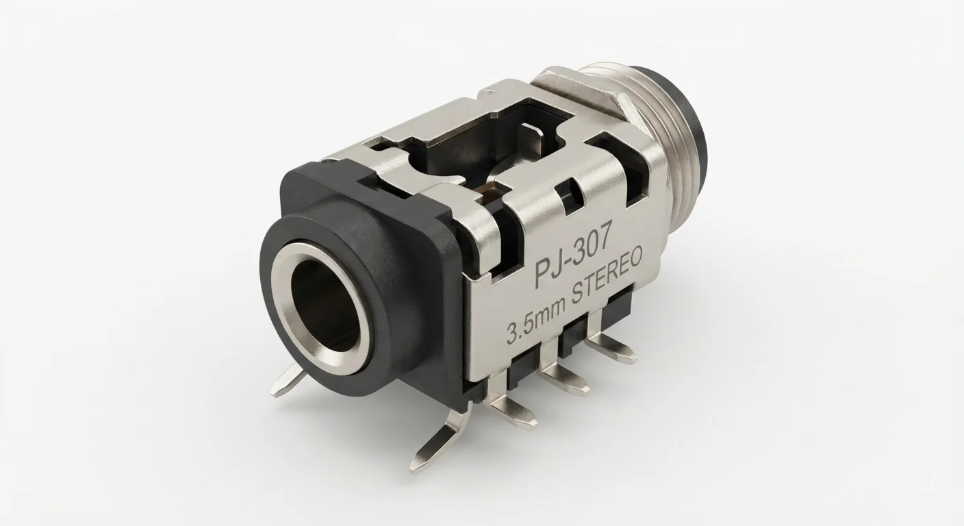
Product-style illustration of 3.5 mm Audio Jack; not a verified physical pin layout
MiscellaneousBeginner

3.5 mm Audio Jack: Map TRS Contacts

Identify tip, ring and sleeve with an unpowered plug and meter. Do not infer solder-terminal order or connect audio directly to ESP32 GPIO.
MiscellaneousSupply: Passive connector; no power requirement or voltage conversion.Signal: Audio can be bipolar or exceed GPIO limits. No direct audio-to-ADC connection in this exercise.Protection: A finished ADC audio input needs designed bias, filtering and voltage limiting. ESP32 GPIO is not an audio amplifier or a 5 V tolerant input.
View Guide
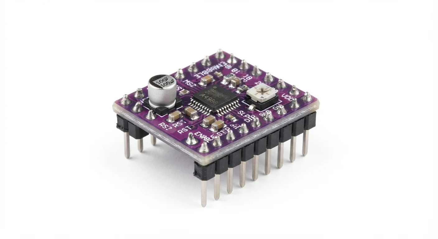
Product-style illustration of A4988 Stepper Driver; not a verified physical pin layout
MotorsBeginner

A4988 Stepper Driver: Current Limit and First Steps

Drive a documented bipolar stepper with STEP/DIR, separate motor power and a verified current limit. Carrier color cannot identify a driver or sense resistors.
MotorsSupply: Reference VDD 3–5.5 V, worked 3.3 V; VMOT 8–35 V, worked regulated 12 V. ESP32 remains USB powered; no 12 V connection to DevKit.Signal: 3.3 V STEP/DIR/ENABLE with VDD at 3.3 V. No motor output connects to GPIO.Protection: Common ground, short suitable power wiring, ≥47 µF / ≥25 V electrolytic near VMOT for this 12 V setup. Set coil current from real Rs/motor rating; no blanket 2 A carrier promise. No hot-plugging.
View Guide
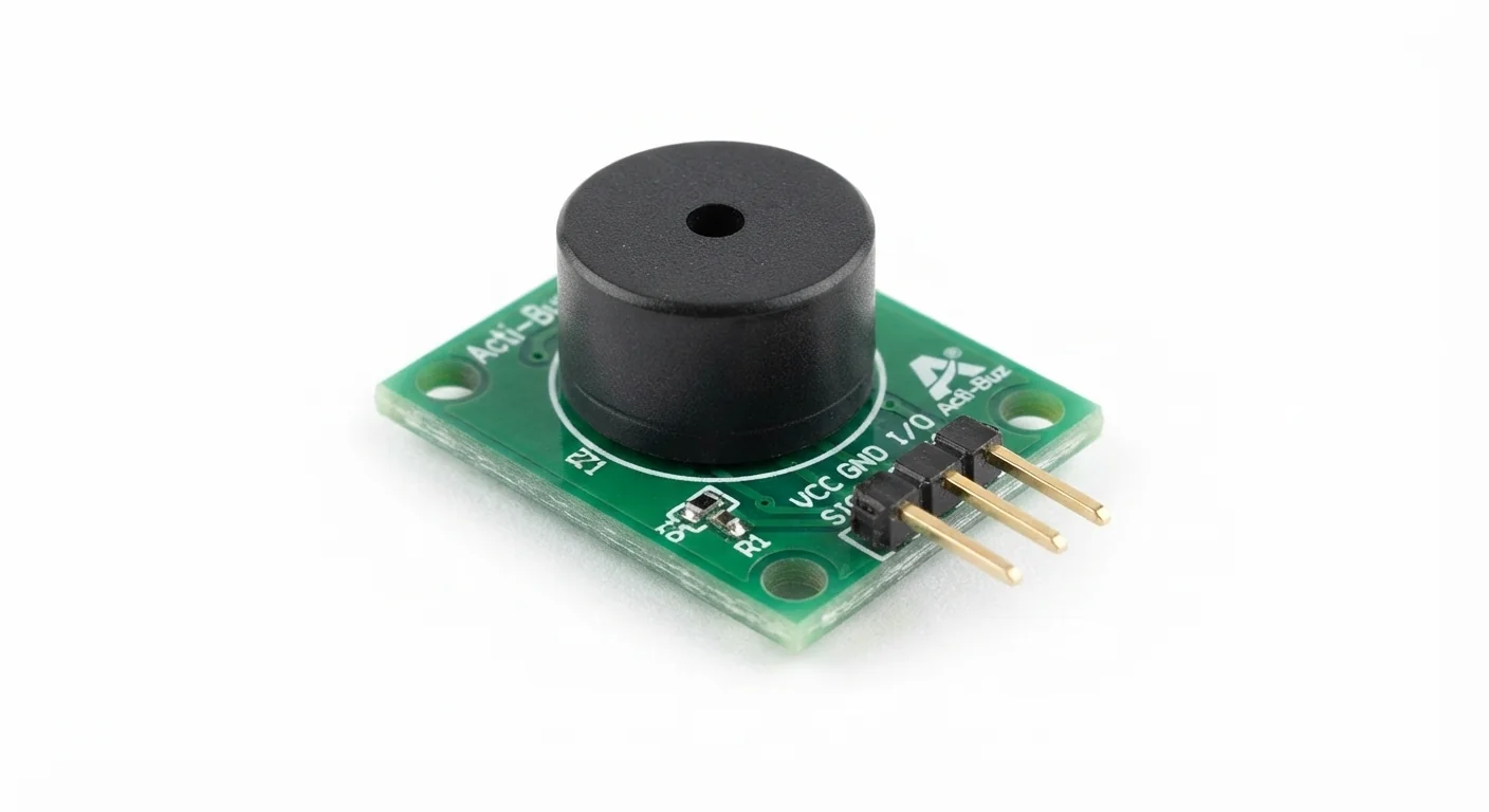
Product-style illustration of Active Buzzer Module; not a verified physical pin layout
ActuatorsBeginner

Active Buzzer Module: Safe ESP32 On/Off Control

Switch a documented active buzzer through an NPN transistor. Keep buzzer power off the GPIO and distinguish a powered signal terminal from a low-current logic input.
ActuatorsSupply: Regulated external 5 V for the documented KY-012; reference operating range includes 3.3–5 V.Signal: GPIO25 → 680 ohm → NPN base. No 5 V terminal connects to ESP32 GPIO.Protection: Shared ground, 100 kOhm base-emitter pull-down and a documented low-side transistor. Never drive an unknown buzzer load directly.
View Guide
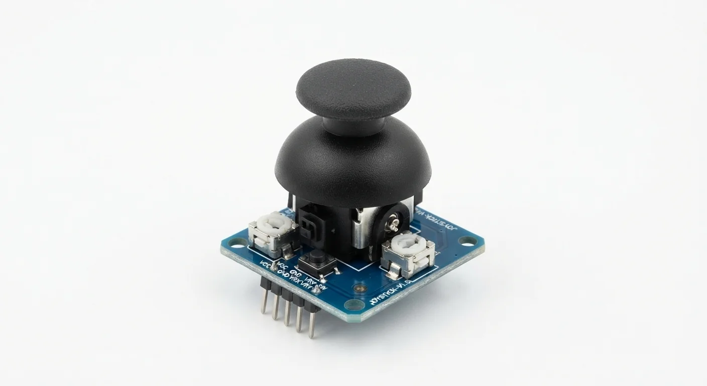
Product-style illustration of Analog Joystick; not a verified module pinout
Input DevicesBeginner

Analog Joystick: ESP32 Wiring and Axis Readings

Read two joystick axes on classic ESP32 ADC1 pins and its push switch on GPIO27. Power a verified passive potentiometer module at 3.3 V to keep axis outputs ESP32-safe.
Input DevicesSupply: 3.3 V for the documented passive joystick used here.Signal: VRx/VRy between GND and the 3.3 V rail; SW pulls GPIO27 to GND.Protection: Do not connect 5 V wiper outputs or 5 V pull-ups; verify the actual module circuit.
View Guide
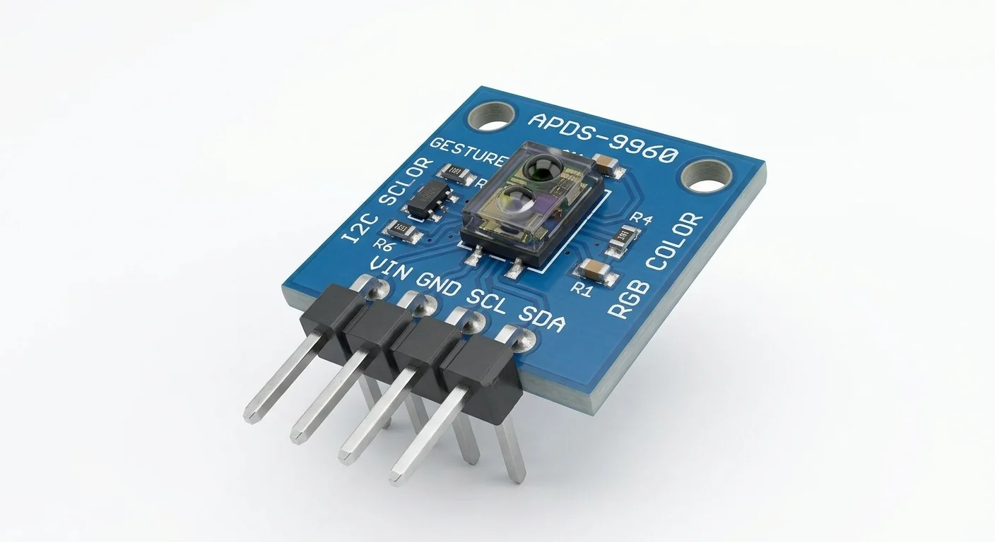
Product-style illustration of APDS-9960 Sensor; not a verified physical pin layout
SensorsBeginner

APDS-9960 Sensor: ESP32 RGB, Light and Gesture Inputs

Start with raw RGB and clear-channel readings at I2C address 0x39. Gesture and proximity modes need their own setup and interpretation.

SensorsSupply: Reference Adafruit VIN to 3.3 V. Bare-chip VDD is 2.4–3.6 V; its LED supply is separate.Signal: SDA21/SCL22 with ESP32-side pulls at 3.3 V, even if a different board accepts 5 V supply.Protection: No 5 V on an undocumented generic board. Reference regulation/level shifting is not inferred from artwork.
View Guide
Product-style illustration of a generic BME280 breakout module with pin header labels
SensorsBeginner

BME280 ESP32 Sensor Wiring and Code

Connect a BME280 to ESP32 at 3.3 V. Check SDA/SCL labels, detect 0x76 or 0x77, and read temperature, humidity and pressure with Arduino.
Temperature, humidity, and barometric pressureSupply: 3.3 V breakout in this wiringSignal: 3.3 V I2C pull-upsProtection: Bare Bosch chip: VDD 1.71–3.6 V, VDDIO 1.2–3.6 V. A regulator alone does not make I2C 5 V-safe; verify breakout pull-ups and level shifting.
View Guide
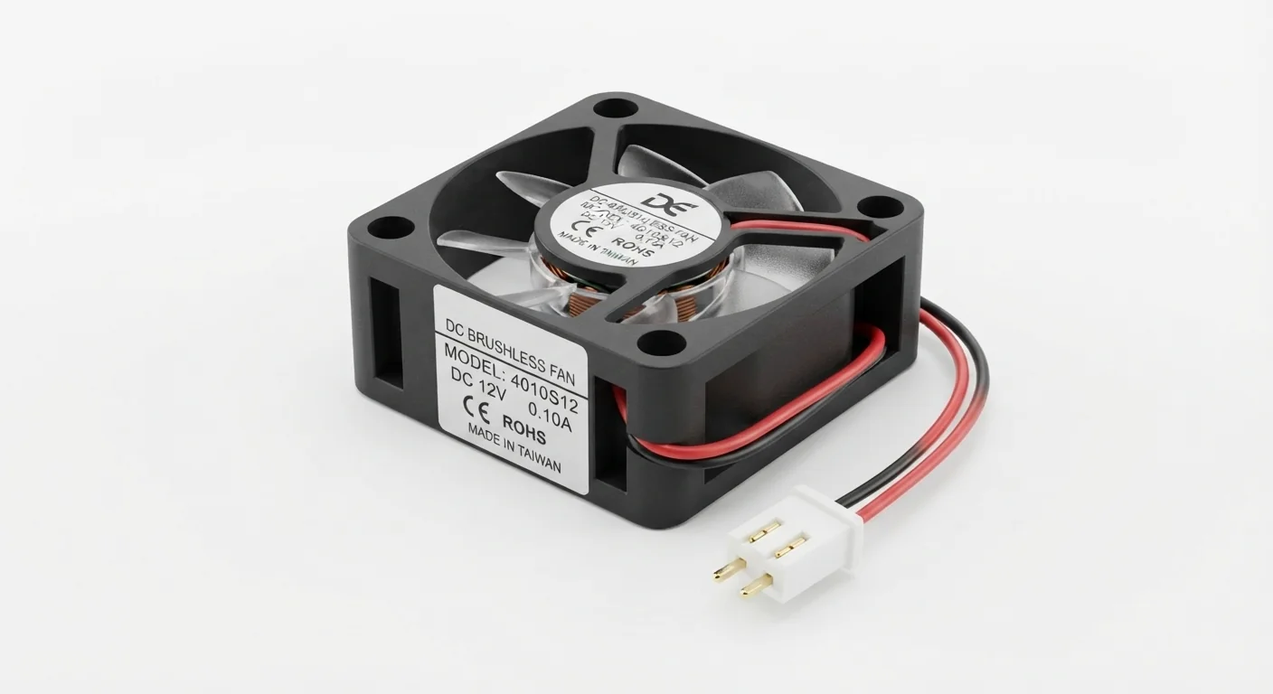
Product-style illustration of DC Brushless Fan; not a verified physical pin layout
MotorsBeginner

DC Brushless Fan: Separate Power and Safe Setup

Identify the rated supply before powering a cooling fan. Use external power and keep fan leads away from ESP32 GPIO.
MotorsSupply: Rated external DC supply; worked reference 12 V. Never fan power from GPIO or DevKit 3V3.Signal: No ESP32 signal connection in this exercise. Tachometer and PWM interfaces require separate documentation and compatible pull-ups.Protection: Confirm polarity and current budget before power. Use insulated suitable wiring; no mains supply assembly or motor current through GPIO/breadboard rails.
View Guide
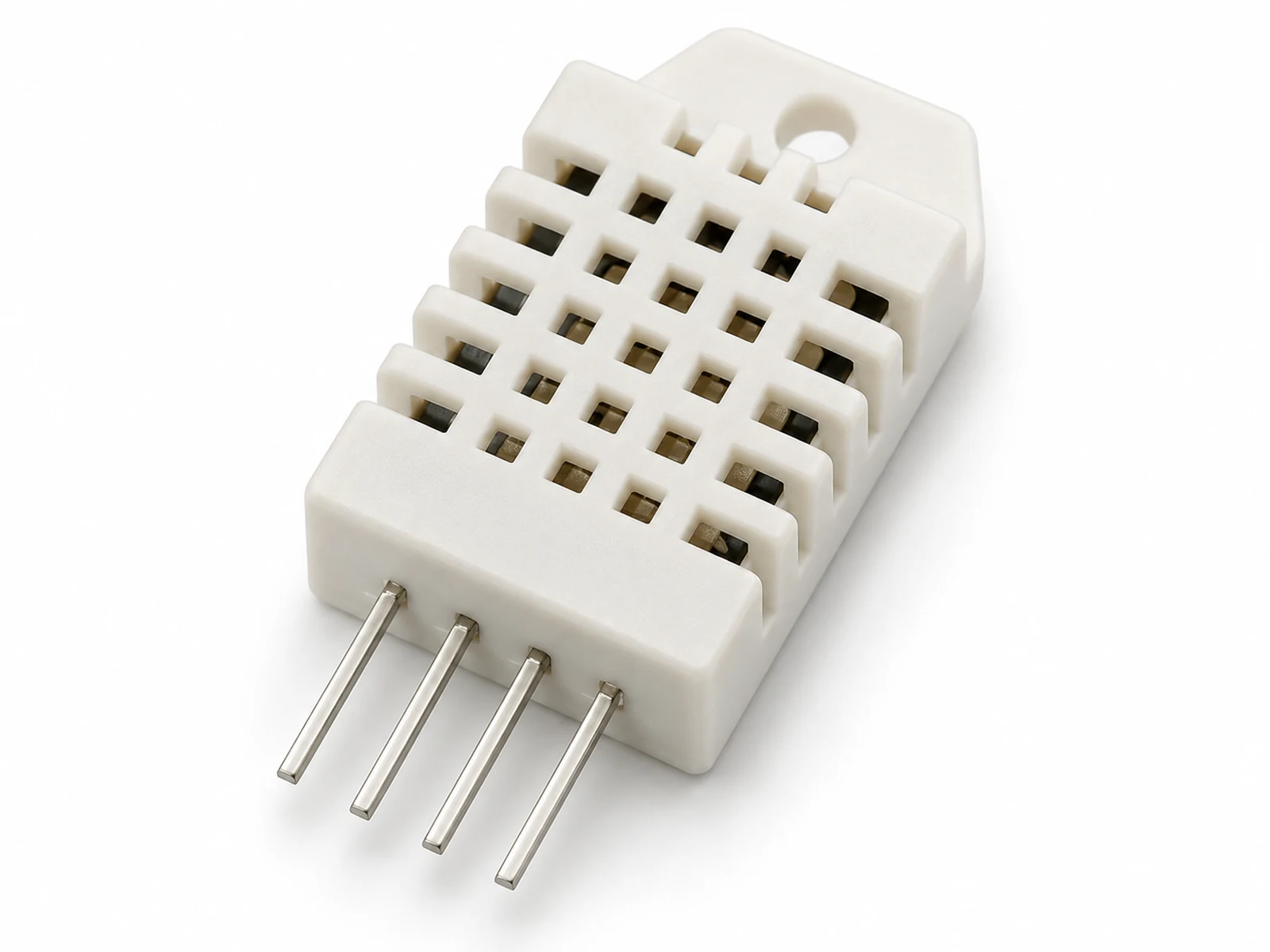
DHT22 with ESP32: Wiring, Readings and Troubleshooting
SensorsBeginner

DHT22 with ESP32: Wiring, Readings and Troubleshooting

Read air temperature and humidity with a DHT22 on ESP32. Identify bare sensors and modules, wire a 3.3 V data pull-up, and diagnose failed readings.
SensorsSupply: 3.3 V in this wiringSignal: DATA pulled up to 3.3 VProtection: Aosong DHT22 sensor supply range is 3.3–6 V; check module ratings. Keep DATA pull-up at 3.3 V; a module pull-up to 5 V needs correction or level shifting.
View Guide
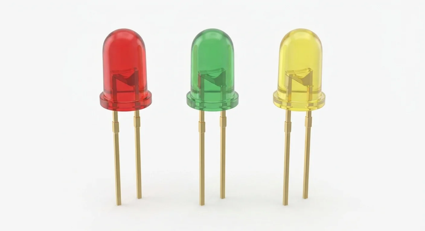
Product-style illustration of Discrete LEDs; not a verified part or physical pin layout
Output DevicesBeginner

Discrete LEDs: Polarity, Resistors and ESP32 Blink

Identify an ordinary two-lead indicator LED and blink a red LED through a 470 ohm resistor. Check polarity and current limits before connecting it.
Output DevicesSupply: GPIO25 supplies the example through 470 ohms; no 5 V connection.Signal: 3.3 V GPIO output; HIGH lights the correctly oriented LED.Protection: One series resistor per LED; choose from actual forward-voltage/current limits. Never connect an LED directly across a GPIO and ground.
View Guide
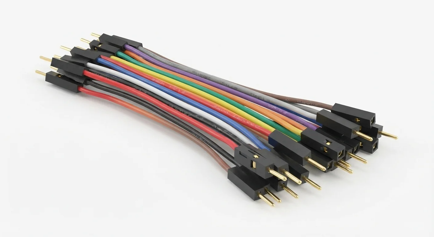
Product-style illustration of Dupont Jumper Wires; not a verified physical pin layout
MiscellaneousBeginner

Dupont Jumper Wires: Check Connections Before Power

Choose the right ends and check continuity. Jumper wires connect nodes; they do not regulate voltage or guarantee a current rating.
MiscellaneousSupply: Passive conductor; no generated voltage or regulation.Signal: A jumper passes the connected signal voltage unchanged. Connecting 5 V through it still endangers ESP32 GPIO.Protection: No universal current rating for this assortment. Keep motor/heater/high-current supply paths on rated wiring and connectors.
View Guide
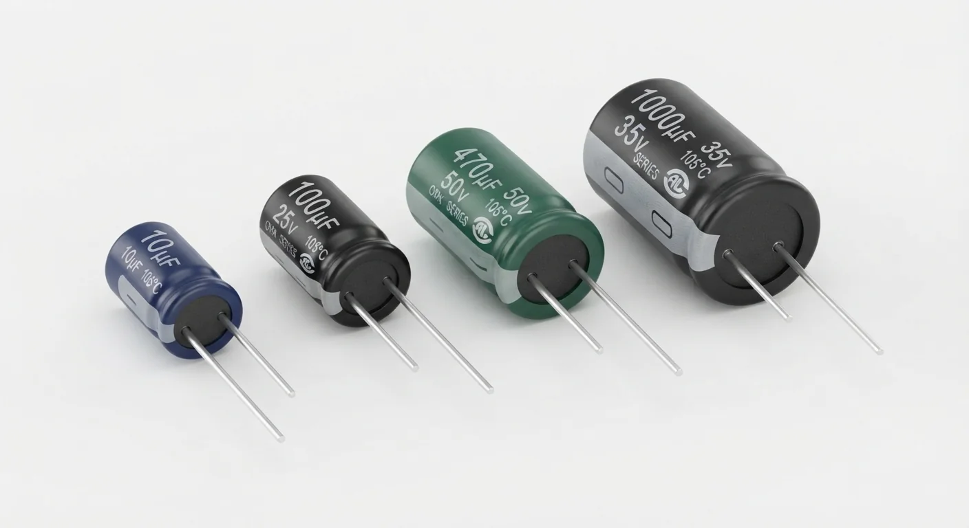
Product-style illustration of Electrolytic Capacitors; not a verified physical pin layout
Power ComponentsBeginner

Electrolytic Capacitors: Polarity and Low-Voltage Power Support

Read capacitance and voltage ratings, identify polarity and try a low-voltage charge/discharge exercise. A capacitor supports a supply; it cannot replace one.
Power ComponentsSupply: Passive part used within rated DC voltage/polarity/temperature/ripple current. Exercise: 5 V on a ≥10 V part.Signal: No signal output or GPIO connection. A capacitor does not level-shift or protect ESP32 from overvoltage.Protection: Charge through 1 kOhm in this exercise. Disconnect supply before resistor discharge and check residual voltage. Do not short leads or use salvaged mains/high-voltage parts.
View Guide
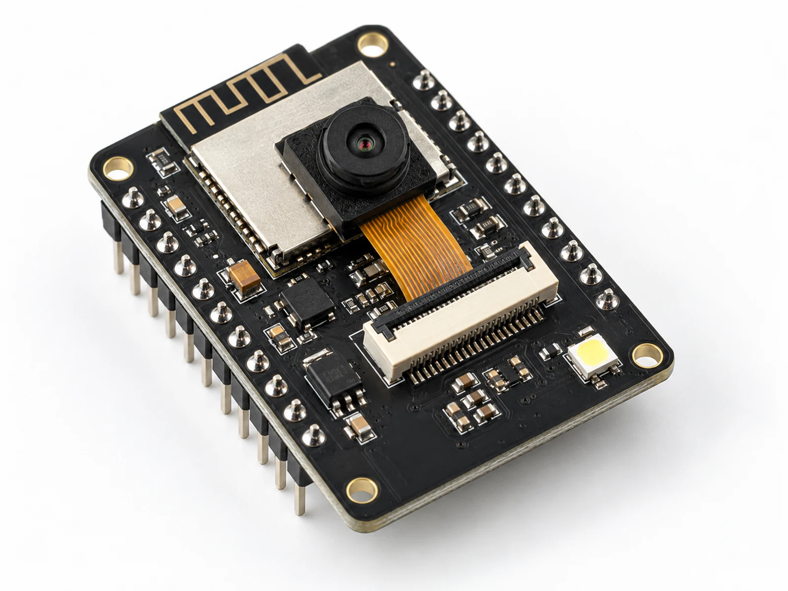
ESP32-CAM (AI-Thinker)
BoardsIntermediate

ESP32-CAM (AI-Thinker)

AI-Thinker ESP32-CAM board with an integrated OV2640 camera, fixed camera pin map, FTDI upload wiring, 5 V power guidance, and privacy-first local camera use.
AI-Thinker ESP32-CAMSupply: 5 V AI-Thinker board inputSignal: 3.3 V GPIO / UARTProtection: Use 3.3 V UART logic even when the board is powered at 5 V; verify the exact board schematic.
View Guide
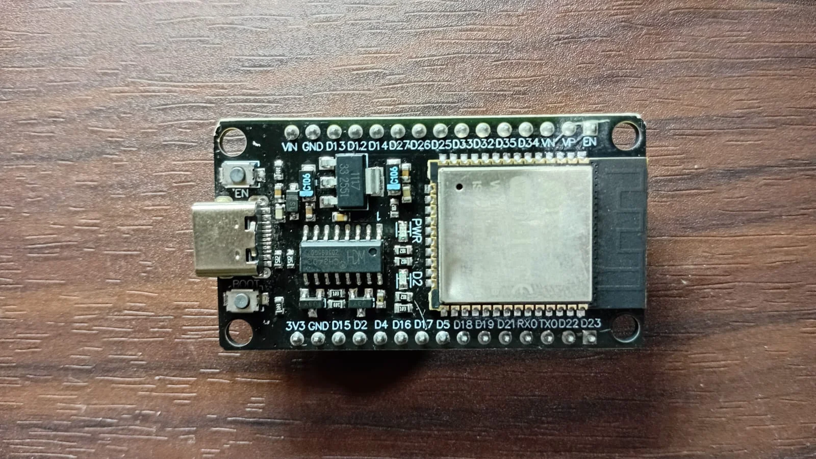
Owner-supplied ESP-32-marked USB-C development board; manufacturer and exact module revision unverified
BoardsBeginner

ESP32 DevKit: First Use, Power and GPIO Guide

Start with a classic ESP32-WROOM DevKit: USB setup, 3.3 V GPIO, pin labels, safe beginner choices, and practical upload troubleshooting.
BoardsSupply: USB / 5 V board inputSignal: 3.3 V GPIOProtection: Never apply 5 V to GPIO; use level shifting for higher-voltage signals. Verify clone power pins and use one power source.
View Guide
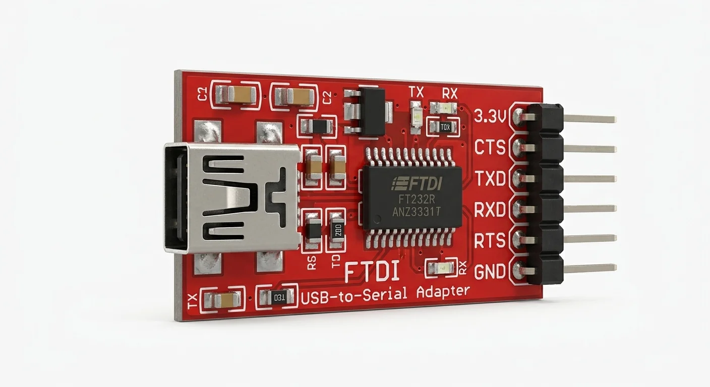
Product-style illustration of FT232R Serial Adapter; not a verified physical pin layout
Communication ModulesBeginner

FT232R Serial Adapter: ESP32 UART Diagnostics

Connect a documented 3.3 V UART adapter to a separate ESP32 serial port. Check signal voltage before wiring; a supply jumper is not proof of safe TX levels.
Communication ModulesSupply: Adapter uses its USB; ESP32 uses DevKit USB. Leave adapter VCC/3V3/5V outputs disconnected.Signal: Documented 3.3 V non-inverted TTL UART only; ESP32 GPIO is not 5 V tolerant. Main chip supply is not the UART signal voltage.Protection: Common ground, crossed TX/RX; no RS-232 levels or adapter DTR/RTS/reset/power connections in this exercise.
View Guide
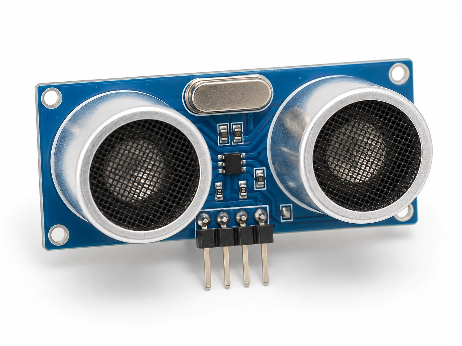
HC-SR04 Ultrasonic Distance Sensor
SensorsBeginner

HC-SR04 Ultrasonic Distance Sensor

HC-SR04 ESP32 ultrasonic sensor reference with VCC 5 V, GND, TRIG on GPIO5, ECHO on GPIO18 through a 10 kOhm / 20 kOhm divider, distance code, and troubleshooting.
About 2 cm to 400 cmSupply: 5 V HC-SR04 supplySignal: ECHO needs level reductionProtection: Use the documented ECHO divider or a suitable level shifter before ESP32 GPIO. TRIG is TTL on the referenced module; verify clone thresholds.
View Guide
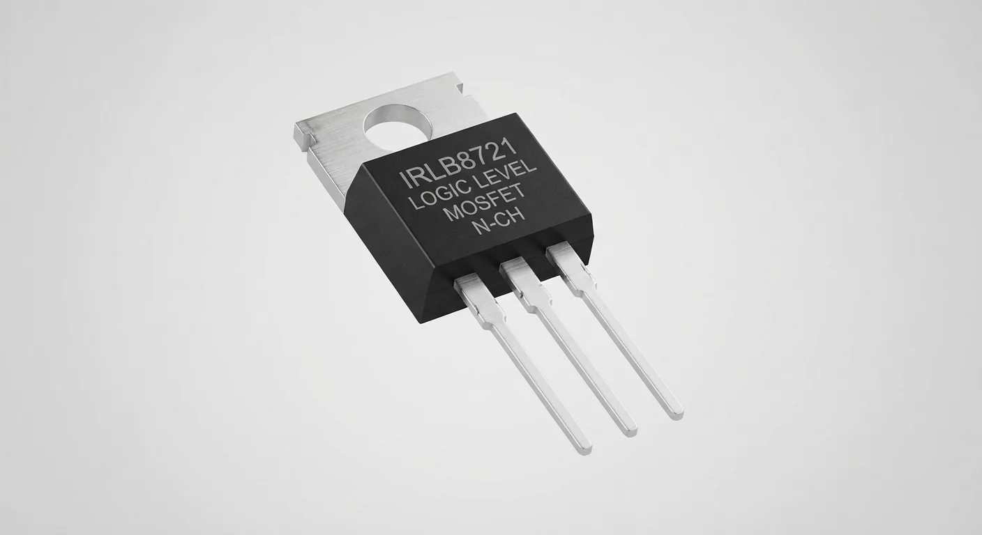
Product-style illustration of IRLB8721 MOSFET; not a verified physical pin layout
Power ComponentsBeginner

IRLB8721 MOSFET: Buffered ESP32 Load Switching

Use an IRLB8721 as a low-side switch with a 5 V gate buffer and a small LED load. Gate threshold does not guarantee low resistance at 3.3 V.
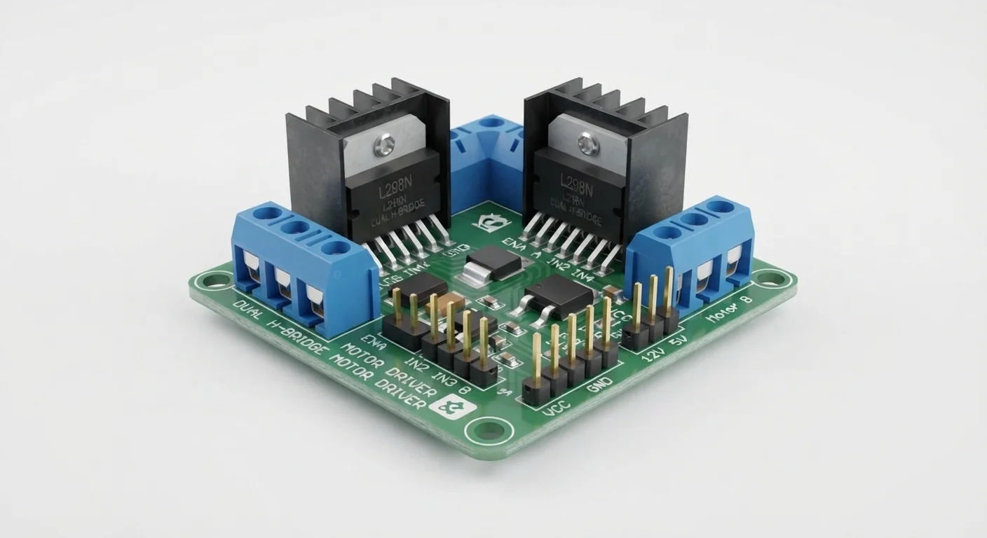
Power ComponentsSupply: External regulated 5 V for the LED and AHCT buffer; source at common GND.Signal: ESP32 GPIO25 drives only the TTL-compatible buffer input. The gate sees buffer output through 1 kOhm.Protection: 10 kOhm input pull-down, 100 kOhm gate-source pull-down, 100 nF buffer bypass and 1 kOhm LED resistor. Never put 5 V on ESP32 GPIO.
View Guide
Product-style illustration of L298N Motor Driver; not a verified part or physical pin layout
MotorsIntermediate

L298N Motor Driver: Power, Enable and Safe Direction Test

Understand separate motor and logic supplies, 3.3 V control and enable inputs. Try one unloaded low-voltage motor only after verifying the actual board schematic.
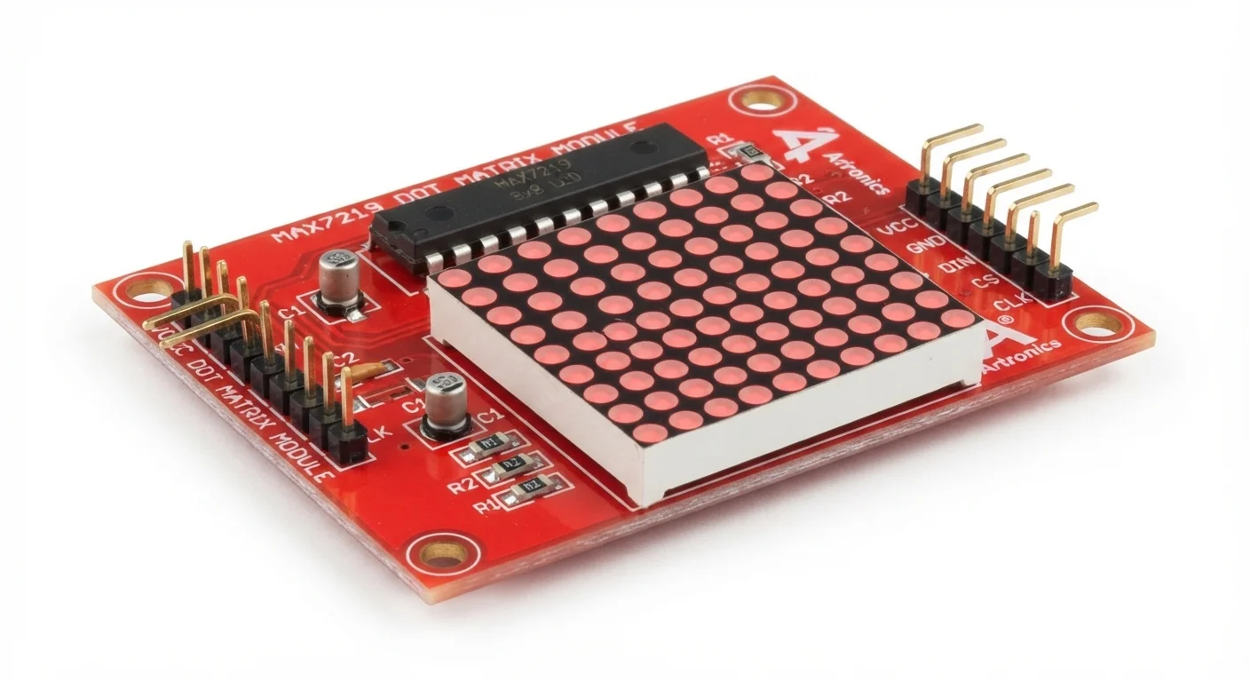
MotorsSupply: Example motor rail: external 6 V; logic rail: regulated 5 V through a board-documented external-input configuration. Never power the motor from ESP32 3.3 V or GPIO.Signal: L298 chip IN/EN HIGH threshold is 2.3 V minimum; 3.3 V control is suitable only if the board has no conflicting 5 V pull-ups or interface. Common ground required.Protection: Disable the onboard regulator only by the exact board instructions before applying external logic power. Remove any documented ENA-to-5 V jumper before GPIO control. Add 10 kiloohm IN1/IN2/ENA pull-downs; qualify protection, supply current and temperature.
View Guide
Product-style illustration of MAX7219 LED Matrix; not a verified module pinout
DisplaysBeginner

MAX7219 LED Matrix: Power, Wiring and First Pattern

Connect one MAX7219 8x8 matrix to a classic ESP32 using a regulated 5 V supply and a 3.3-to-5 V buffer. Select the actual module mapping before displaying a pattern.
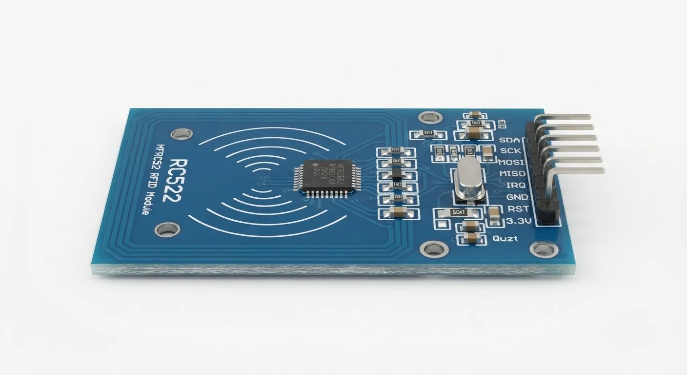
DisplaysSupply: Regulated external 5 V for matrix and buffer; MAX7219 chip operating range 4.0–5.5 V.Signal: ESP32 3.3 V into SN74AHCT125; buffered signals to matrix DIN/CLK/LOAD.Protection: Common ground, decoupling and sized supply wires; keep 5 V away from ESP32 GPIO/3V3.
View Guide
Product-style illustration of MFRC522 RFID Reader; not a verified physical pin layout
Communication ModulesBeginner

MFRC522 RFID Reader: Read a Tag UID with ESP32

Connect a documented 3.3 V RC522 SPI reader, check its register response and print a compatible tag UID. A UID is identification data, not secure authentication.
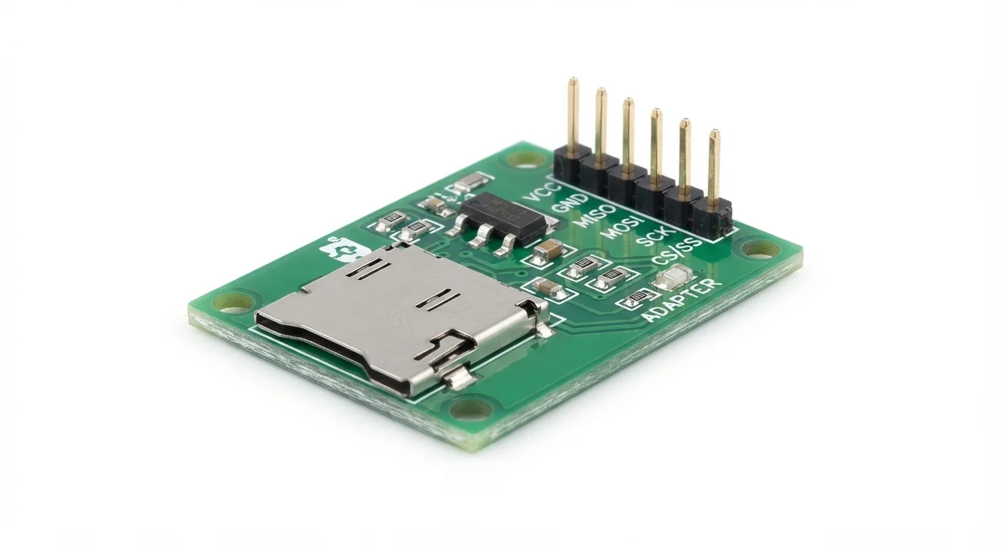
Communication ModulesSupply: ESP32 3.3 V only for this documented 3.3 V module; check the DevKit regulator budget.Signal: SPI and reset use 3.3 V logic; common ground.Protection: No 5 V supply or host signals. Disconnect before wiring and keep SPI wires short.
View Guide
Product-style illustration of microSD SPI Module; not a verified physical pin layout
Communication ModulesBeginner

microSD SPI Module: Read a File Safely

Mount a prepared card over SPI and read a small text file. Check carrier voltage circuitry before connecting an ESP32.
Communication ModulesSupply: Reference 4682 at 3.3 V only; never 5 V. Verify regulator capacity/decoupling for card bursts on actual board.Signal: SPI clock/data/CS in 3.3 V domain. Generic adapter supply label does not prove level compatibility.Protection: Common ground and short wires; power off for insertion/removal. No unknown 5 V pull-ups or shared positive supplies.
View Guide
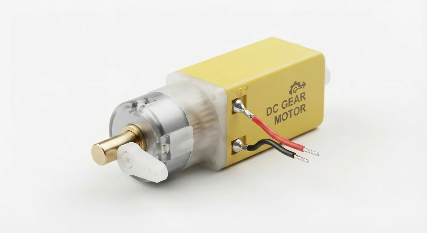
Product-style illustration of Mini DC Gear Motor; not a verified physical pin layout
MotorsBeginner

Mini DC Gear Motor: Power and First Rotation

Identify motor voltage and current before powering a gearbox. A motor needs separate power and a suitable driver; GPIO cannot supply it.
MotorsSupply: Worked reference starts at regulated3 V within its3–6 V range; actual motor rating must be known.Signal: No direct GPIO connection. Future H-bridge needs compatible3.3 V inputs and separate motor power/common ground.Protection: Suitable load wiring, secure unloaded motor, fingers clear and no stall test. Do not route motor current through GPIO/unknown breadboard rails.
View Guide
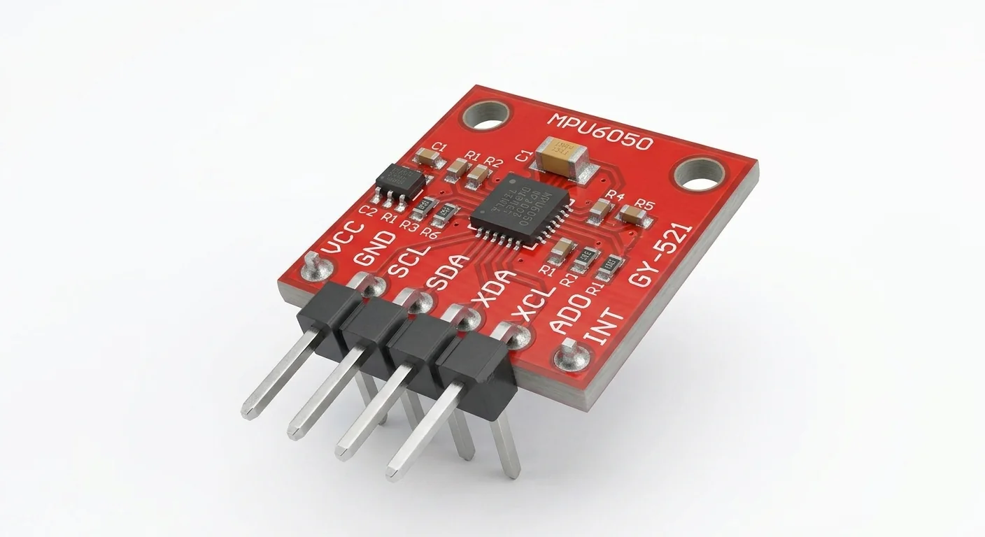
Product-style illustration of MPU6050 Motion Sensor; not a verified physical pin layout
SensorsBeginner

MPU6050 Motion Sensor: ESP32 Acceleration and Gyroscope

Read acceleration in m/s² and angular velocity in rad/s over I2C. Distinguish gravity, gyro bias and chip temperature from calibrated orientation.
SensorsSupply: Reference Adafruit VIN to 3.3 V; bare-chip and unknown GY-521 requirements are separate.Signal: GPIO21/22 I2C at 3.3 V; reference breakout has level shifting and pull-ups.Protection: Keep ESP32-side pulls at 3.3 V. Do not infer 5 V tolerance from a generic VCC label or bypass an undocumented regulator.
View Guide
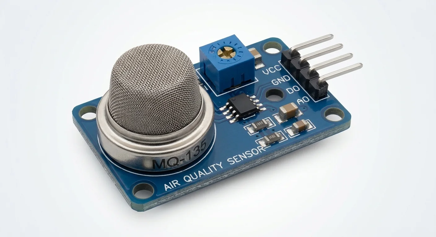
Product-style illustration of MQ-135; not a verified physical pin layout
SensorsBeginner

MQ-135: Protected ESP32 Analog Readings

Read an MQ-135 analog signal without exposing ESP32 GPIO to 5 V. Separate broad gas sensitivity from a selective CO2 measurement or an air-quality index.
SensorsSupply: External regulated 5.0 V ±0.1 V for this documented carrier; heater and loop requirements differ from ESP32 logic. Never power the heater from a GPIO or assume the DevKit 3.3 V regulator can supply it.Signal: AO → 10 kohm → node → GPIO32; node → 10 kohm → GND. At AO=5.1 V, ideal node=2.55 V; with 1% resistor worst-case ratio, about 2.576 V. Verify with meter before connecting ESP32. DO is unused.Protection: 100 nF from node to GND, shared ground and separate positive supplies. Divider is required even with high ADC attenuation. Avoid powered signals into an unpowered ESP32; disconnect together. This is not a safety gas alarm.
View Guide
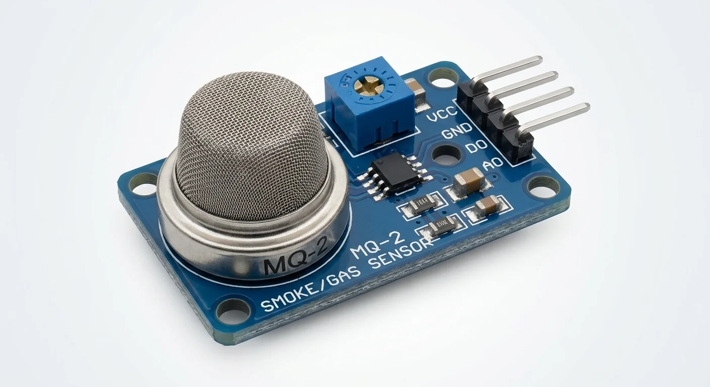
Product-style illustration of MQ-2; not a verified physical pin layout
SensorsBeginner

MQ-2: Protected ESP32 Analog Readings

Observe a heated MQ-2 module’s analog output through a voltage divider. Learn why a raw reading is not a calibrated smoke or combustible-gas alarm.
SensorsSupply: External regulated 5.0 V ±0.1 V for this documented carrier; heater and loop requirements differ from ESP32 logic. Never power the heater from a GPIO or assume the DevKit 3.3 V regulator can supply it.Signal: AO → 10 kohm → node → GPIO32; node → 10 kohm → GND. At AO=5.1 V, ideal node=2.55 V; with 1% resistor worst-case ratio, about 2.576 V. Verify with meter before connecting ESP32. DO is unused.Protection: 100 nF from node to GND, shared ground and separate positive supplies. Divider is required even with high ADC attenuation. Avoid powered signals into an unpowered ESP32; disconnect together. This is not a safety gas alarm.
View Guide
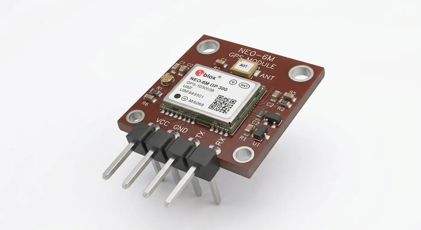
Product-style illustration of NEO-6M GPS; not a verified physical pin layout
Communication ModulesBeginner

NEO-6M GPS: Read UART Sentences Before Parsing

Check a documented NEO-6M UART connection and inspect raw NMEA sentences. Serial activity and a valid satellite fix are different results.
Communication ModulesSupply: External regulated 3.3 V to the carrier’s documented compatible input. Budget for carrier and antenna in addition to receiver; no GPIO power and no inferred universal board current rating.Signal: Verified native 3.3 V UART TX to ESP32 GPIO16 RX. GPS RX is unused; ESP32 GPIO17 is configured TX but left unwired.Protection: Common GND; separate positive rails. Do not connect GPS TX while ESP32 is unpowered. Antenna and connector require the purchased board documentation; not interchangeable by appearance.
View Guide
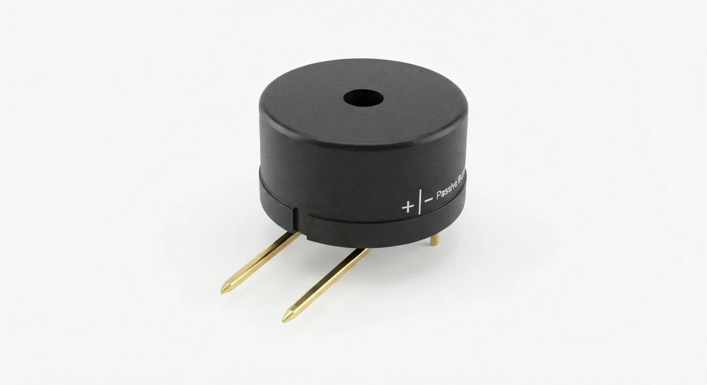
Product-style illustration of Passive Buzzer; not a verified part or physical pin layout
Output DevicesBeginner

Passive Buzzer: Piezo Assumptions and ESP32 Tones

Distinguish passive sounders from active buzzers and play a short tone with Arduino-ESP32 3.x. The example is for a documented piezo, not an unidentified magnetic buzzer.
Output DevicesSupply: Piezo receives only the GPIO25 waveform through 1 kiloohm; no external power rail in this example.Signal: LEDC produces a 0–3.3 V, 50% duty waveform. GPIO is LOW during silence.Protection: The 1 kiloohm series resistor limits edge/short-circuit current to about 3.3 mA at 3.3 V. It does not make an unknown magnetic load suitable or replace a manufacturer drive circuit.
View Guide
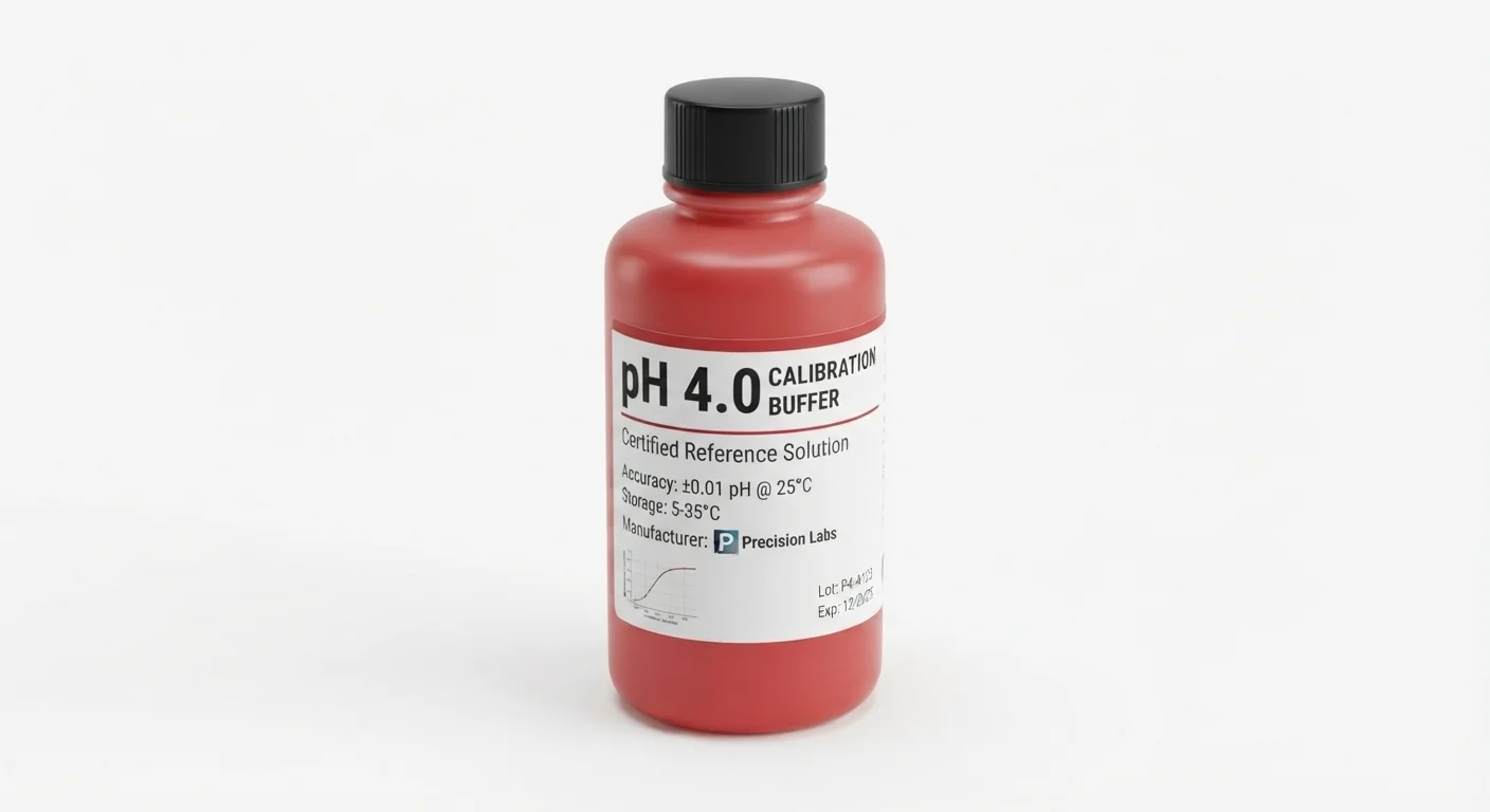
Product-style illustration of pH 4 Calibration Buffer; not a verified physical pin layout
MiscellaneousBeginner

pH 4 Buffer: Acidic Calibration Point

Use a documented acidic reference after the neutral point to check the electrode response across a lower-pH range.
MiscellaneousSupply: No electrical supply; chemical reference only.Signal: No GPIO or analog output. The separate meter/interface determines ESP32 voltage compatibility.Protection: Keep liquids away from powered electronics. Follow actual product handling/SDS and do not return used buffer to the bottle.
View Guide
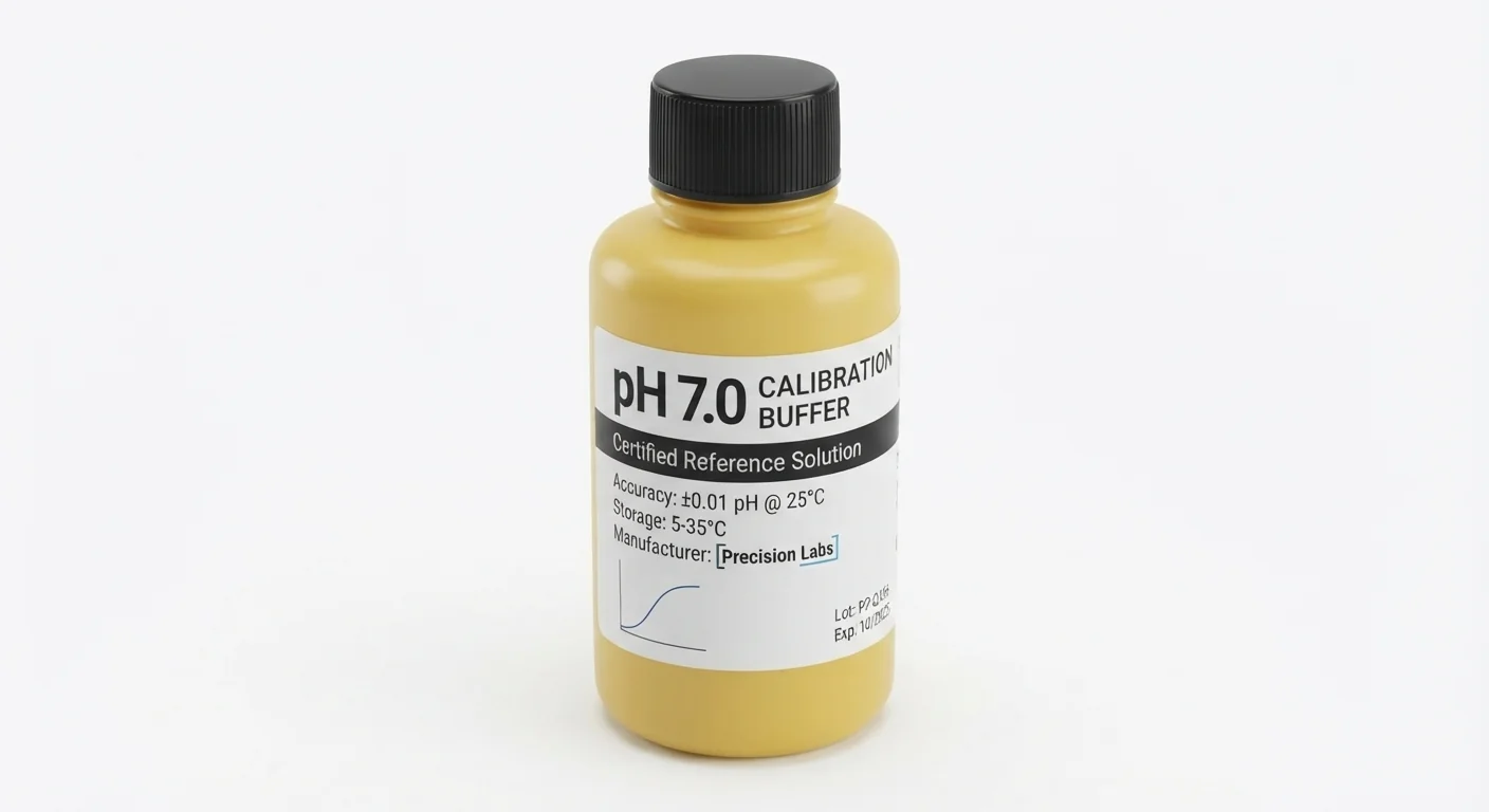
Product-style illustration of pH 7 Calibration Buffer; not a verified physical pin layout
MiscellaneousBeginner

pH 7 Buffer: Neutral Reference and Offset

Establish the near-neutral calibration point before assessing a second buffer. Check stabilization and reference selection.
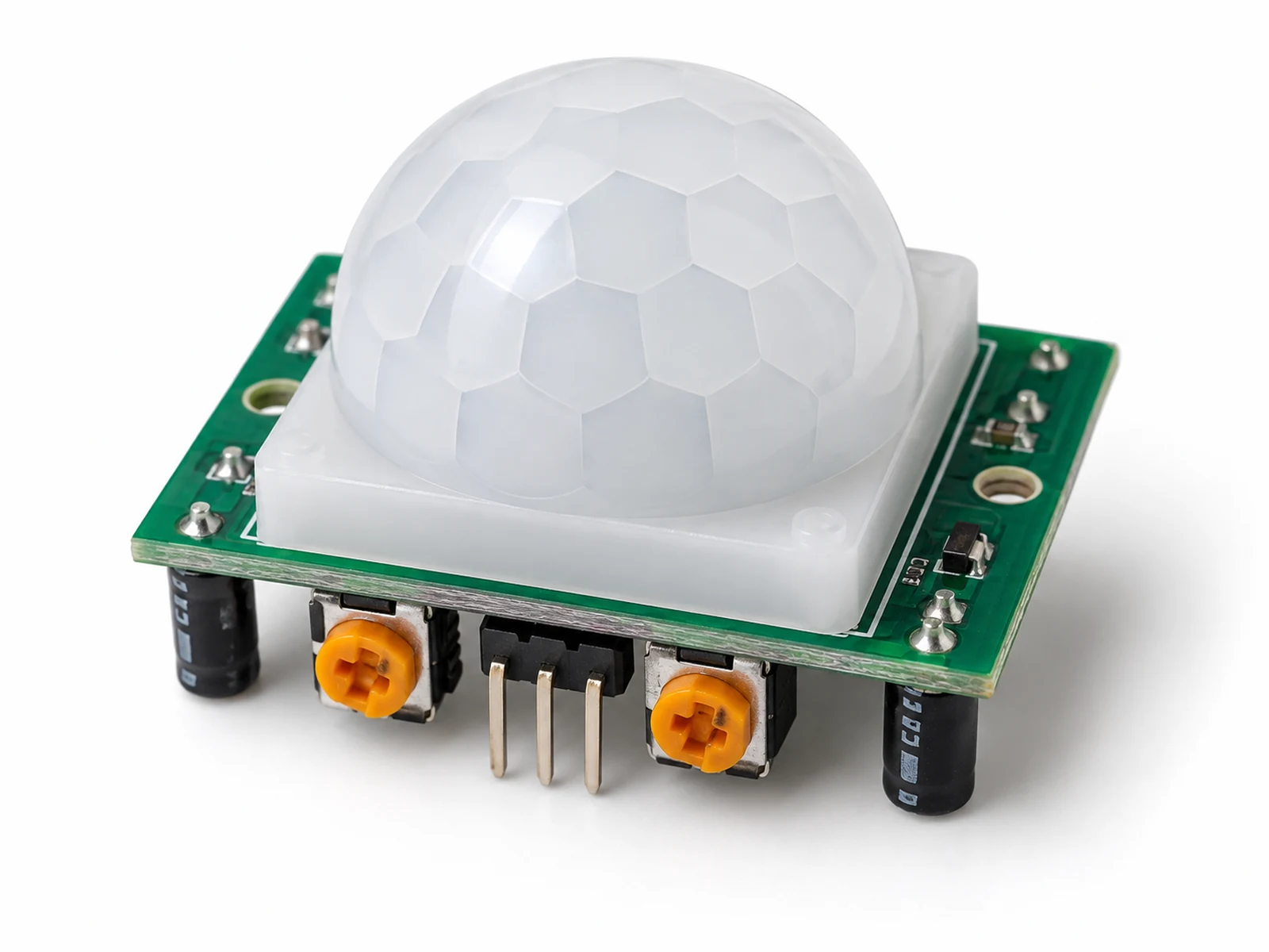
MiscellaneousSupply: No electrical supply; chemical reference only.Signal: No GPIO or analog output. The separate meter/interface determines ESP32 voltage compatibility.Protection: Keep liquids away from powered electronics. Follow actual product handling/SDS and do not return used buffer to the bottle.
View Guide
HC-SR501 PIR Motion Sensor
Input DevicesBeginner

HC-SR501 PIR Motion Sensor

HC-SR501 PIR sensor ESP32 reference with VCC, GND, OUT on GPIO27, digital HIGH motion output, warm-up time, sensitivity/delay controls, code, and false-trigger fixes.
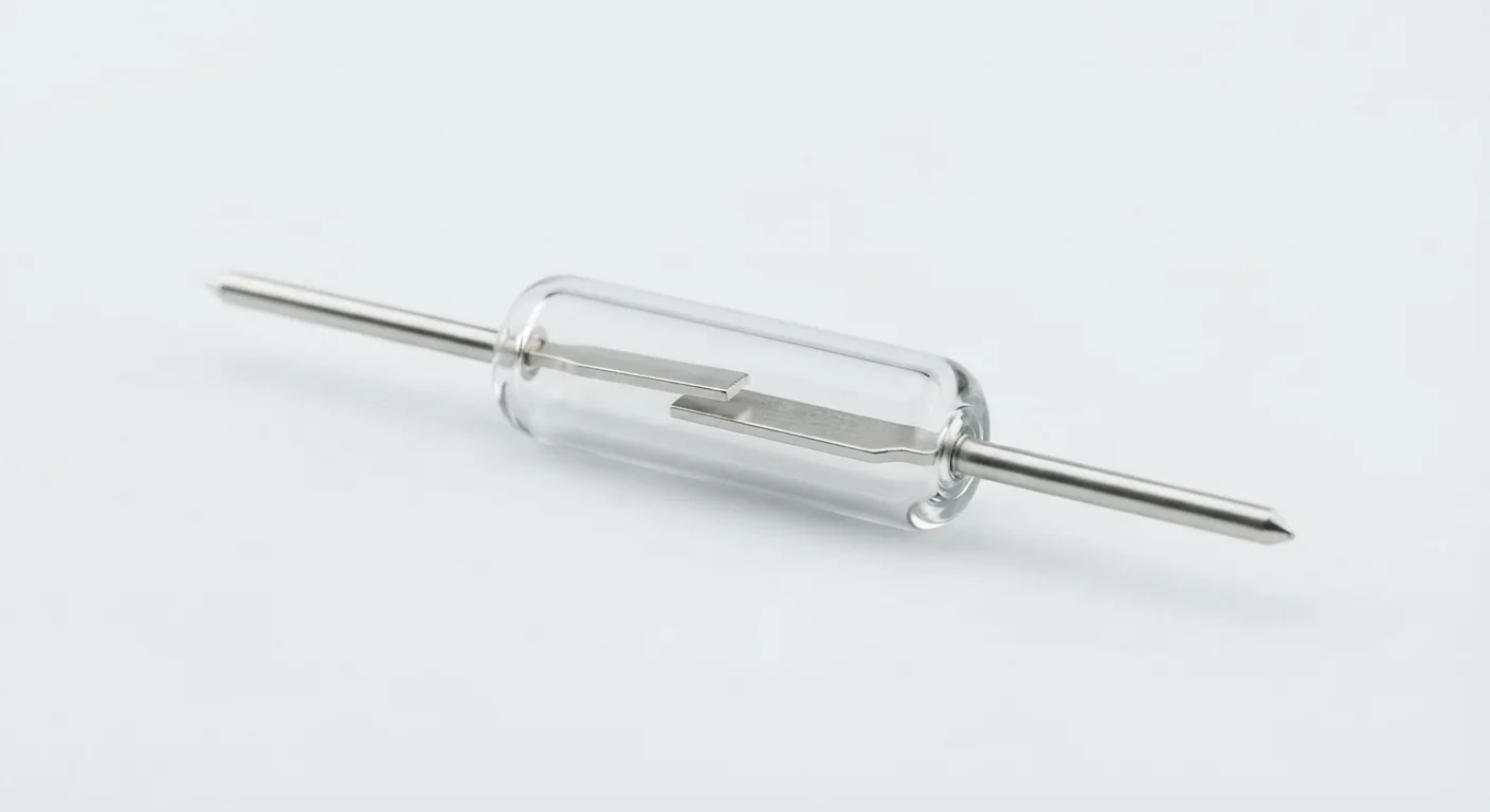
Moving warm bodiesSupply: 5 V HC-SR501 in this wiringSignal: OUT typically 3.3 V; verifyProtection: Check the actual module OUT voltage before direct GPIO connection; level shift if above 3.3 V. Supply and OUT voltage are different ratings.
View Guide
Product-style illustration of Reed Switch; not a verified module pinout
Input DevicesBeginner

Reed Switch: ESP32 Magnetic Input and Debouncing

Read a normally open reed switch on GPIO33 with INPUT_PULLUP. A nearby magnet closes the contact to ground; stable-state code filters contact bounce.
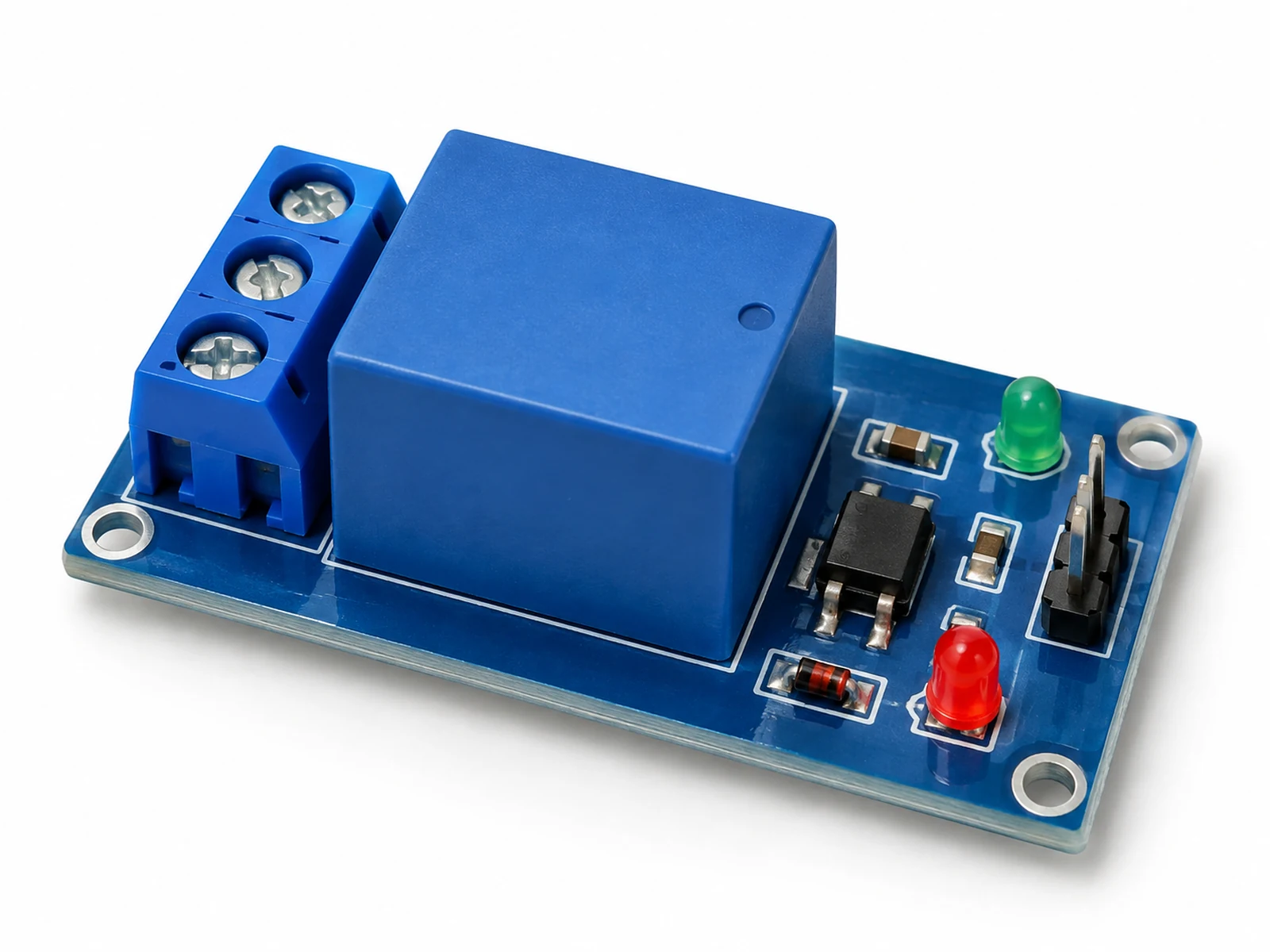
Input DevicesSupply: No active supply; a dry contact connects GPIO33 to GND.Signal: 3.3 V GPIO input held HIGH by INPUT_PULLUP; closed contact reads LOW.Protection: Use only a low-voltage sensing circuit; no mains or motor load. Handle glass/leads without stressing the seal.
View Guide
Generic single-channel relay module photo; not identification or pin order for the supported STEMMA example
Power and SwitchingBeginner

1-Channel Relay Module

Learn relay contacts and ESP32 control using a documented active-HIGH STEMMA non-latching relay and a low-voltage LED test. Other module inputs require their own specifications.
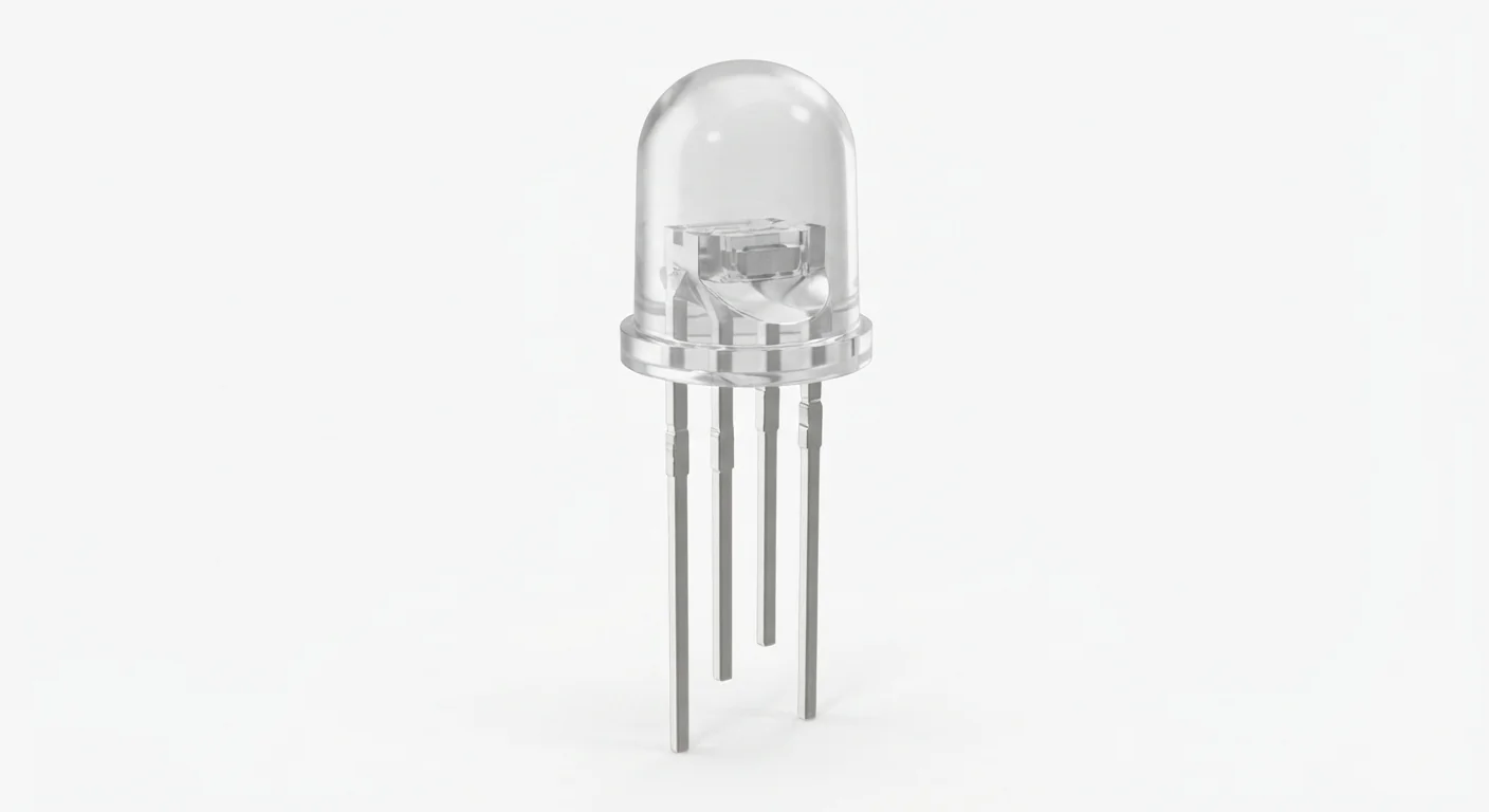
Model dependent; supported STEMMA example active HIGHSupply: Typically 5 V; verify coilSignal: IN compatibility unverifiedProtection: Check exact module schematic and trigger thresholds. Use a suitable transistor/level-shifting interface if 3.3 V control is unsupported or IN is pulled to 5 V; never drive the coil from GPIO.
View Guide
Product-style illustration of Four-Lead RGB LED; not a verified part or physical pin layout
Output DevicesBeginner

Four-Lead RGB LED: Common Terminal and ESP32 Color Test

Identify common-cathode versus common-anode RGB LEDs, use a resistor for each color, and cycle three channels on a classic ESP32.
Output DevicesSupply: No separate rail in this common-cathode example; each GPIO drives a color through 470 ohms.Signal: GPIO25/26/27 are 3.3 V outputs; HIGH turns the selected channel on.Protection: One resistor per channel. Never connect a common anode to 5 V and return its channels directly to ESP32 pins.
View Guide
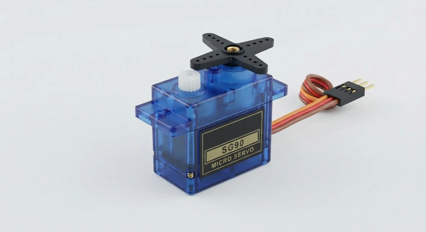
Product-style illustration of SG90 Micro Servo; not a verified module pinout
ActuatorsBeginner

SG90 Micro Servo: External Power and ESP32 Pulses

Control a positional SG90-class servo using Arduino-ESP32 3.x LEDC. Use a documented external supply, common ground and a buffered control signal; begin with small unloaded movements.
ActuatorsSupply: External regulated 4.8 V for a servo documented for that rail and the AHCT buffer. Never ESP32 3V3.Signal: GPIO25 at 3.3 V into buffer; buffer output to servo signal.Protection: Common ground; verify supply surge capacity and servo input limits. Keep external positive rail separate from ESP32 USB/3V3.
View Guide
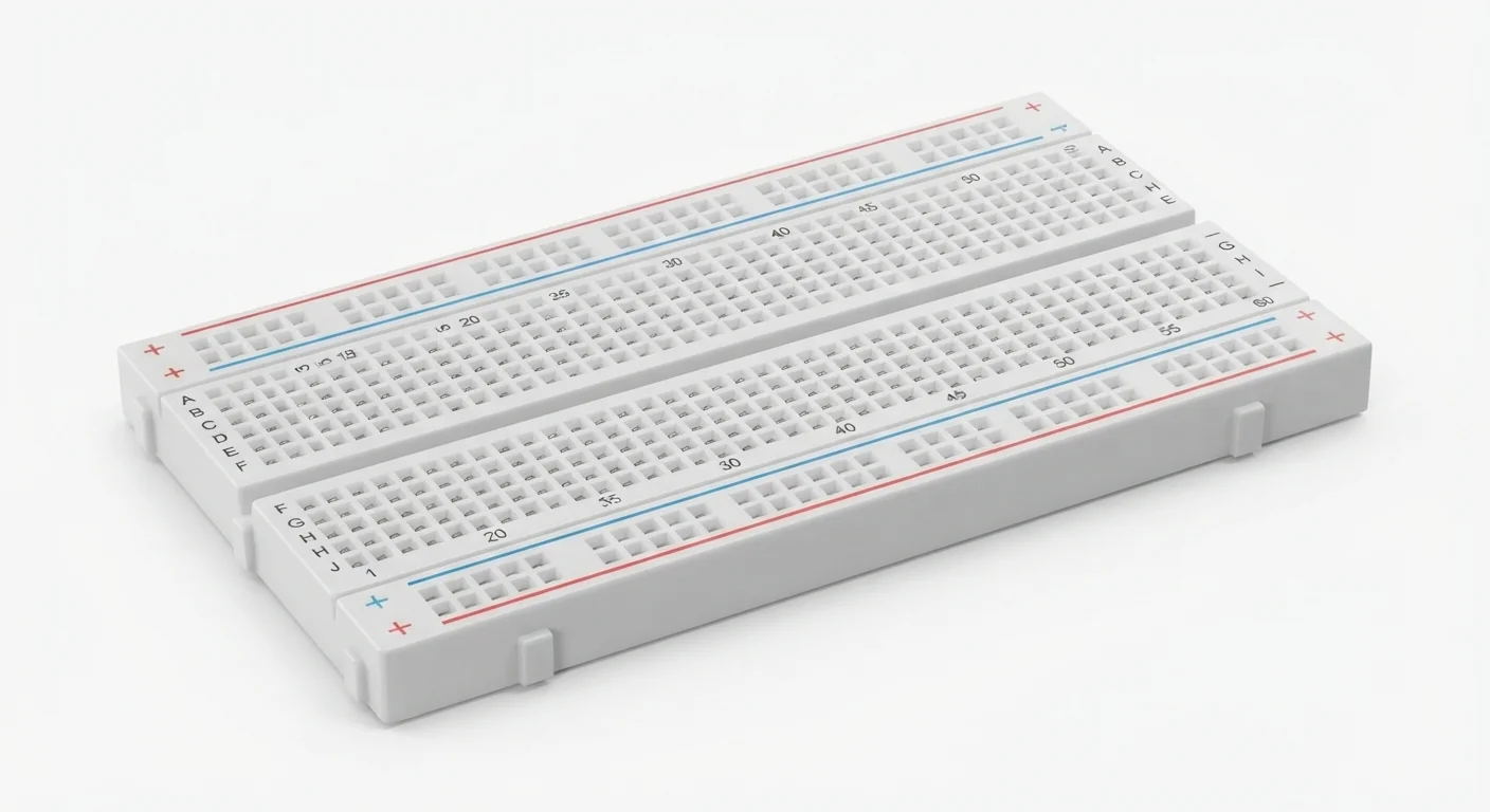
Product-style illustration of Solderless Breadboard; not a verified physical pin layout
MiscellaneousBeginner

Solderless Breadboard: Connections and First LED Circuit

Trace terminal strips and split rails before building. Assemble GPIO25 Blink using separate electrical nodes and a current-limiting resistor.
MiscellaneousSupply: Passive contacts, not a regulator. LED example uses DevKit USB and GPIO25; no breadboard power module needed.Signal: GPIO25 is 3.3 V logic. Separate nodes and 470 ohm series resistor required; rail color does not protect GPIO from 5 V.Protection: Continuity only with all power removed. Keep motor/heater/high-current LED power off unspecified breadboard rails; never mains wiring.
View Guide
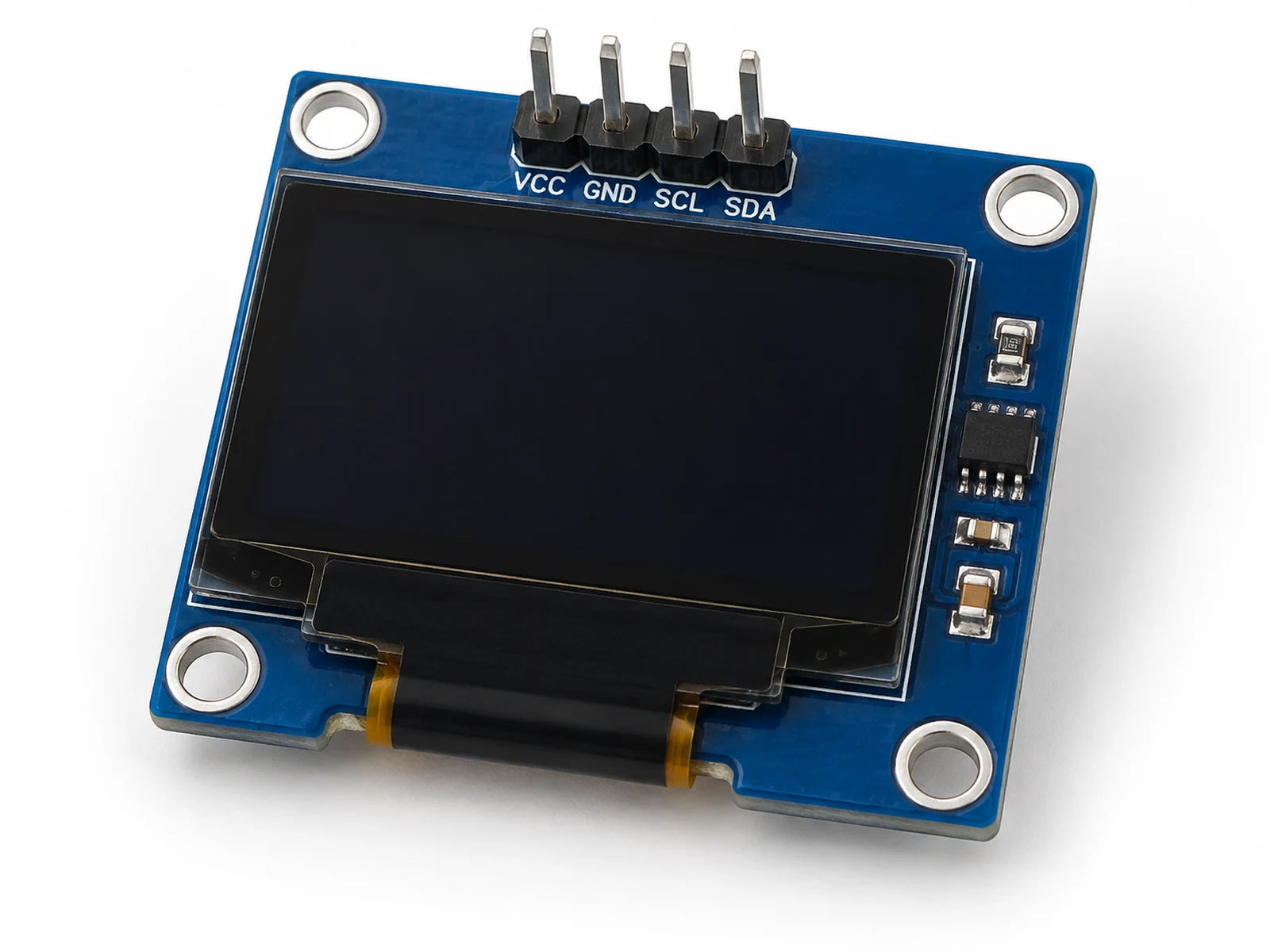
SSD1306 OLED Display with ESP32
DisplaysBeginner

SSD1306 OLED Display with ESP32

SSD1306 OLED ESP32 wiring reference for I2C displays, with VCC, GND, SDA GPIO21, SCL GPIO22, 0x3C/0x3D address checks, Arduino libraries, and blank-screen fixes.
128 x 64 pixelsSupply: 3.3 V-compatible module onlySignal: SDA/SCL pull-ups to 3.3 VProtection: SSD1306 chip VDD is 1.65–3.3 V; board power circuitry varies. Check module ratings and pull-ups. For a 5 V-powered board with 5 V bus pull-ups, use I2C level shifting.
View Guide
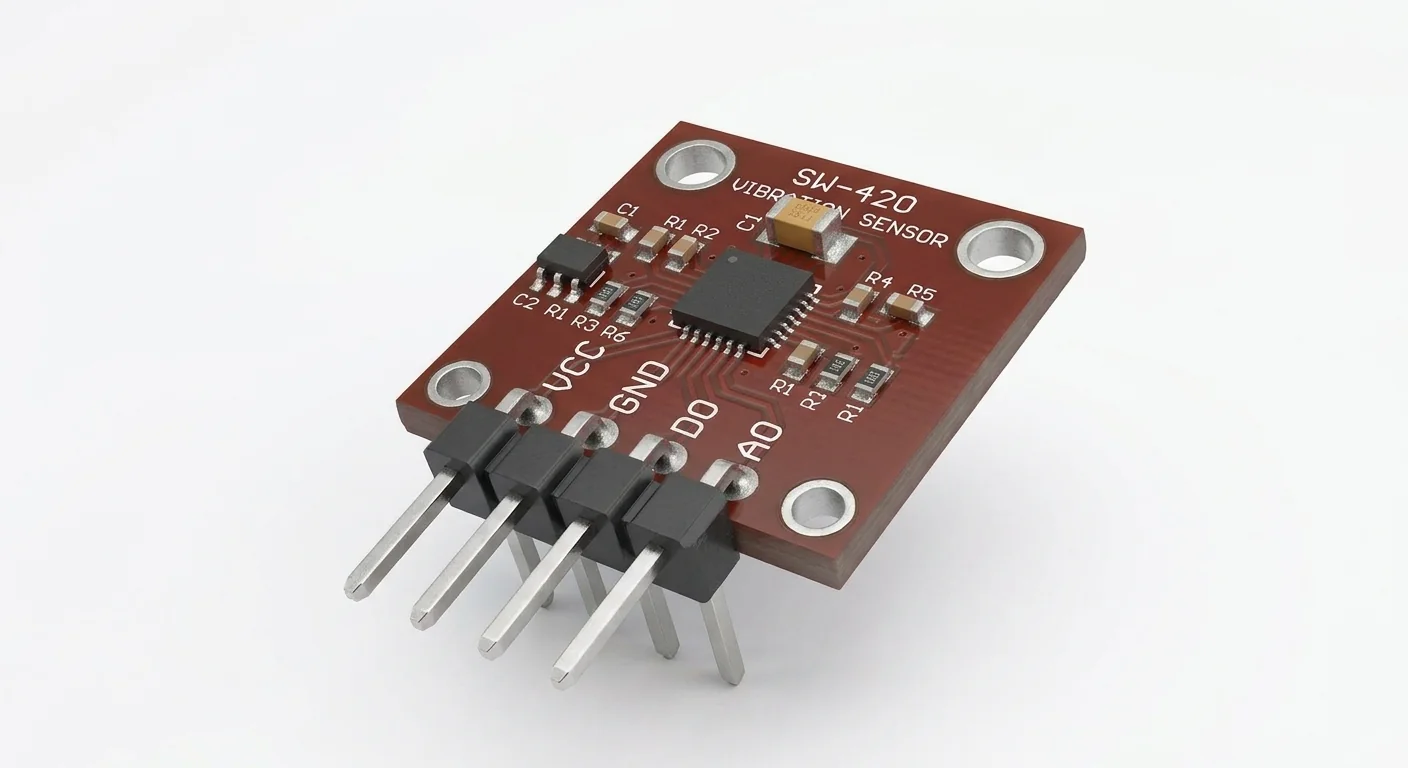
Product-style illustration of SW-420; not a verified physical pin layout
SensorsBeginner

SW-420: Observe Digital Vibration Events

Capture short digital pulses from a documented SW-420 comparator module. Treat the event count as electrical transitions, not calibrated acceleration or independent impacts.
SensorsSupply: 3.3 V from a DevKit with enough regulator budget for the documented Seeed module; its 5 V capability is not permission to expose ESP32 GPIO to 5 V.Signal: Documented 3.3 V SIG/DO → GPIO27, quiet HIGH and event LOW in the worked reference. Other output polarities need an explicitly matched circuit/code.Protection: Common ground, short wires and verified pin labels. Do not connect unknown AO/DO or 5 V pull-ups directly; use actual schematic and measured levels.
View Guide
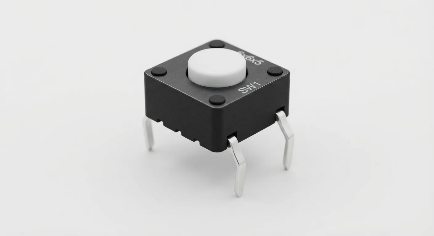
Product-style illustration of Tactile Button; not a verified module pinout
Input DevicesBeginner

Tactile Button: Terminal Pairing and ESP32 Input

Identify the two internally joined terminal pairs before wiring a four-leg tactile switch. Connect one contact group to GPIO27 and the other to GND, then debounce the active-LOW input.
Input DevicesSupply: No active supply for this bare contact; no VCC pin.Signal: GPIO27 with 3.3 V INPUT_PULLUP; press closes to GND.Protection: Confirm terminal groups and breadboard rows. Never wire a bare switch directly between 3.3 V and GND.
View Guide
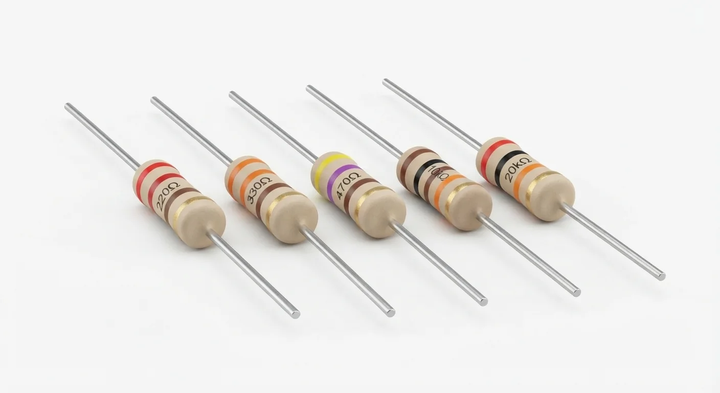
Product-style illustration of Through-Hole Resistors; not a verified module pinout
Power ComponentsBeginner

Through-Hole Resistors: Values and ESP32 LED Wiring

Identify four- and five-band resistor values, check resistance with power off, and choose an LED current-limiting resistor. Try a 470 ohm series resistor with an external LED on GPIO25.
Power ComponentsSupply: No active supply; the example resistor is in series with a GPIO-driven LED.Signal: GPIO25 uses 3.3 V logic; the resistor limits LED current, not logic voltage by itself.Protection: Use documented resistance/power rating; verify LED polarity and current. Disconnect power before resistance measurements.
View Guide
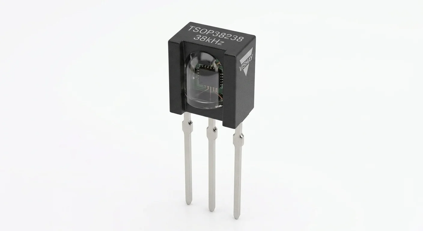
Product-style illustration of TSOP38238 IR Receiver; not a verified physical pin layout
Input DevicesBeginner

TSOP38238 IR Receiver: Decode a Remote with ESP32

Power a documented TSOP38238 at 3.3 V and decode a compatible 38 kHz remote on GPIO27. Follow the manufacturer pin drawing, not the illustration.
Input DevicesSupply: 3.3 V to VS here; documented operating range 2.0–5.5 V.Signal: OUT to GPIO27; powering at 3.3 V references the output to the ESP32 logic rail.Protection: Do not use 5 V supply with OUT directly attached to ESP32. Fit 100 nF near VS/GND; assess extra filtering for noisy supplies.
View Guide
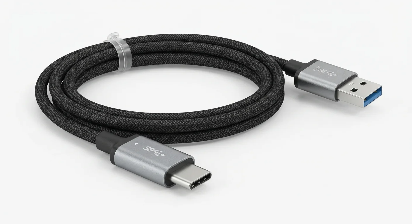
Product-style illustration of USB-A to USB-C Cable; not a verified physical pin layout
MiscellaneousBeginner

USB-A to USB-C Cable: Power Is Not Data

Choose a data-capable cable for the actual ESP32 USB port. Power indicators alone do not prove USB enumeration or upload support.
MiscellaneousSupply: USB power goes through the board designed USB connector/power circuit. Do not expose cable wires or inject USB voltage into GPIO.Signal: USB data pins connect to the USB interface, not arbitrary ESP32 GPIO. Board GPIO remains 3.3 V logic.Protection: Use undamaged documented cables and board input ratings. This page does not authorize USB-PD voltages, power modifications or a universal current rating.
View Guide
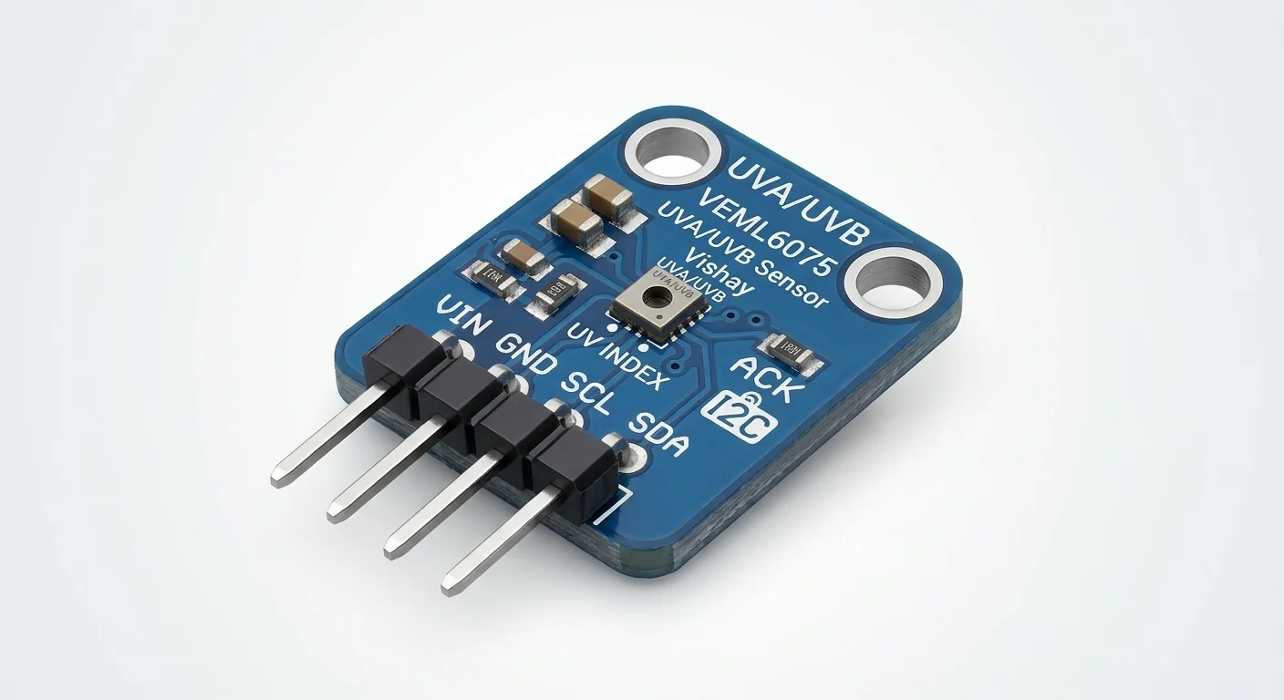
Product-style illustration of VEML6075 UV Sensor; not a verified physical pin layout
SensorsBeginner

VEML6075 UV Sensor: UVA, UVB and Estimated UV Index

Read compensated UVA/UVB counts and an estimated UV index with a documented 3.3 V I2C setup. Do not treat the module as a calibrated exposure instrument.
SensorsSupply: Reference breakout VIN at 3.3 V; its regulator output is left disconnected. Bare-chip supply differs; follow Vishay datasheet.Signal: I2C SDA/SCL pull-ups must reach 3.3 V, never 5 V for ESP32. Reference board powered at 3.3 V.Protection: Common ground. Confirm actual carrier circuit before using a different board; an I2C response does not identify the sensor.
View Guide
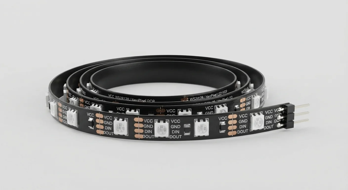
Product-style illustration of WS2812B RGB Strip; not a verified physical pin layout
DisplaysBeginner

WS2812B RGB Strip: One-Pixel ESP32 Test

Start with one documented 5 V WS2812B RGB pixel, buffered data and a correctly sized supply. Check direction and color order before extending the strip.

DisplaysSupply: Regulated external 5 V for the documented pixel and buffer. Do not power a strip from GPIO or the DevKit 3.3 V rail.Signal: GPIO25 at 3.3 V → 5 V AHCT buffer → 330 ohm → pixel DIN. Common ground.Protection: 1000 microfarad supply capacitor with correct polarity and voltage rating, short data wire, buffer bypass and input pull-down.
View Guide