
Before you start
- Board and software
- Low-voltage bench setup as specified below. ESP32 is optional for passive exercises. Coded examples require classic ESP32-WROOM-32/32E DevKit, unused exposed pins, Arduino IDE 2.x and Arduino-ESP32 3.3.2 (review baseline, not a latest-release claim). Other families need their own pin map.
- Supported hardware
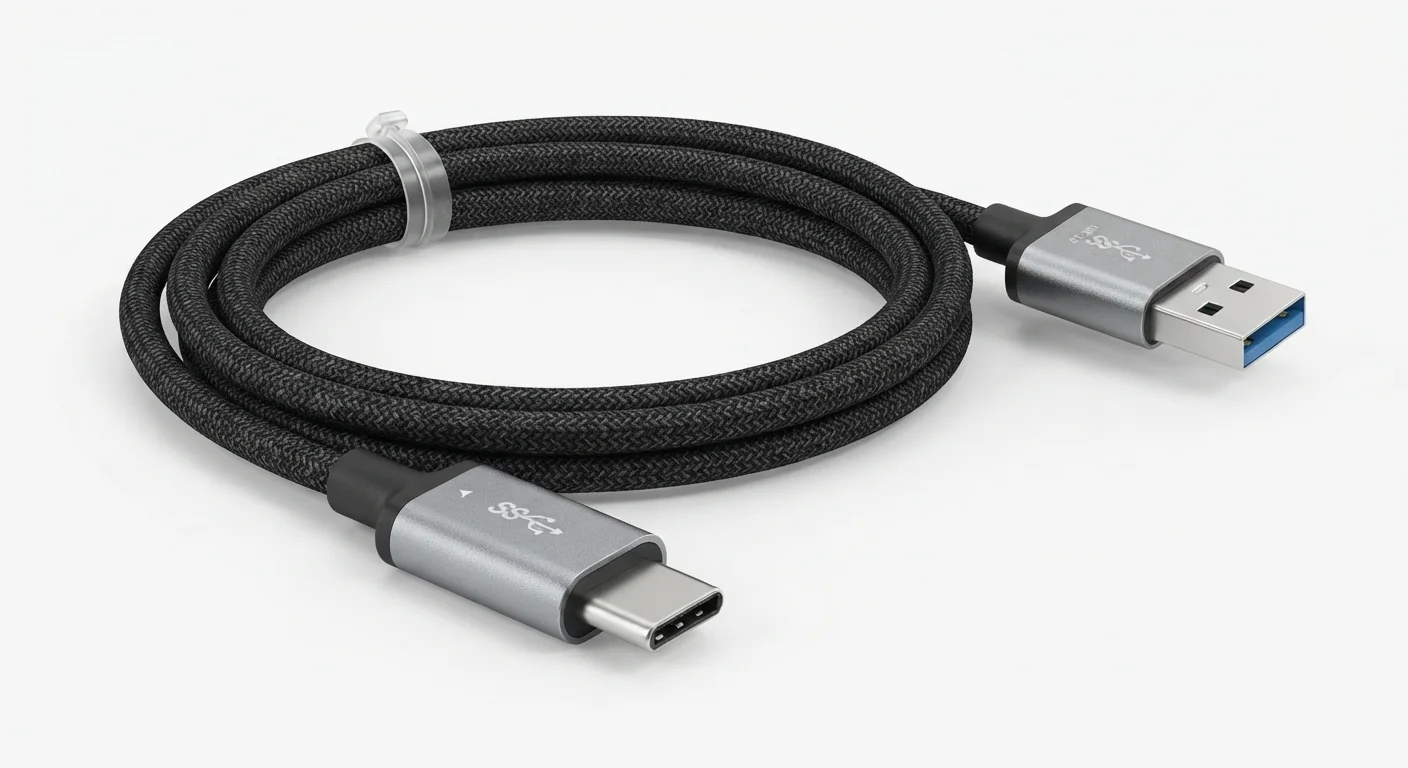
- Approved USB-A to USB-C cable illustration. Data support, USB generation, current rating and certification are not established by the image.
- Prerequisites and parts
- Computer USB-A port, known data-capable A-to-C cable and a board with USB-C receptacle. Many classic DevKits use Micro-B; choose the correct cable instead of forcing the connector. Follow the existing IDE setup guide.
- Libraries
- No firmware or library required for this exercise. Arduino-ESP32 3.3.2 is the site review baseline, not a dependency of this passive setup.
- Expected result
- A known data-capable cable and supported board appear as the expected USB device/port, then accept the existing Serial-only first sketch.
- Verification status
- Documentation and source review only. Not compiled or tested on hardware. The approved product-style illustration identifies a family, not a verified physical pin layout or manufacturer-authenticated board. Follow the logical diagram and documentation for your actual part.
Overview
USB-C describes a connector. It does not, by itself, prove data speed, power capability or firmware-upload support. A board may light up through a cable that cannot carry the data needed for its USB bridge.
On a classic WROOM DevKit, USB commonly connects through a USB-UART bridge. On some newer boards it connects to native USB. Port selection and drivers depend on the actual board and bridge, not on cable shape.
Technical Specifications
Arduino library: No firmware or library required for this exercise
| Specification | Value | Why it matters |
|---|---|---|
| Illustrated ends | USB-A plug and USB-C plug | Match actual computer and board ports. |
| Data capability | Verify with a known working cable/device | Power light is not proof. |
| Upload path | Board/bridge dependent | Use correct OS port and driver. |
Pinout
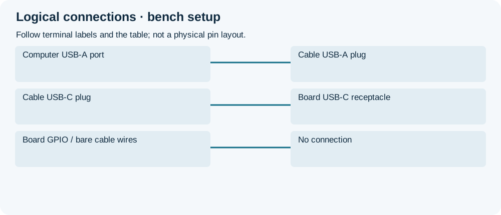
- Computer USB-A port Connection Cable USB-A plug Use documented computer port.
- Cable USB-C plug Connection Board USB-C receptacle Actual board upload connector.
- Board GPIO / bare cable wires Connection No connection Keep the cable intact.
Wiring Diagram
Computer USB port → intact matching cable → board designated USB connector.
| Component terminal | ESP32 / circuit connection | Purpose and qualification |
|---|---|---|
| Computer USB-A port | Cable USB-A plug | Use documented computer port. |
| Cable USB-C plug | Board USB-C receptacle | Actual board upload connector. |
| Board GPIO / bare cable wires | No connection | Keep the cable intact. |
Open wiring diagram at full size (new tab)
-
1
Check actual connector and cable condition.
-
2
Connect through a known data-capable cable; identify enumeration/port.
-
3
Follow IDE guide Serial-only upload and verify its output.
Expected Output
A suitable cable should allow the actual device to enumerate. Successful power-on alone does not confirm data. The Serial-only example in the setup guide separates upload/serial checks from onboard LED assumptions.
How it works
The cable carries power and, if supported, data between compatible ports. USB enumeration identifies the interface; the IDE then uses the selected upload method. Do not install an FTDI driver for a different bridge just because a port is missing.
Troubleshooting
| Problem | Possible cause | Solution |
|---|---|---|
| Power but no port | No data path, wrong bridge driver or connector problem. | Try a known data cable and direct computer port; identify actual USB device. |
| Upload fails after enumeration | Wrong board/port or boot mode. | Follow board-specific IDE/BOOT instructions rather than replacing drivers blindly. |
| Cable does not fit | Different board receptacle. | Use matching Micro-B/C cable; never force. |
Where you use it
- First ESP32 USB upload
- Distinguishing cable faults from IDE or bridge-driver issues
Continue learning
FAQ
No. A USB-C board can still use a USB-UART bridge.
No. GPIO compatibility follows the chip/board circuit.
Technical references
- USB-IF cable and connector specifications — Connector families and specifications; no certification claim for artwork.
- Espressif Arduino installation — Board-package setup baseline.