
Before you start
- Board and software
- Classic ESP32-WROOM-32/32E DevKit with these GPIOs exposed and unused. Arduino IDE 2.x; esp32 by Espressif Systems 3.x (API review baseline 3.3.2, not a latest-version claim). Select the exact board or ESP32 Dev Module for a generic WROOM board. Other ESP32 families need their own pin map. Serial Monitor: 115200 baud.
- Hardware assumption
- A bare, normally open, momentary four-terminal tactile switch with two permanently connected terminal groups. Exact model/physical pairing is unspecified; identify it with continuity or its datasheet. LED-lit, latched and electronic button modules need different circuits. Choose a part documented for low-current 3.3 V contact service; check any minimum-load specification.
- Prerequisites and parts
- First complete Arduino IDE setup and Blink. Button, breadboard, short wires and a continuity meter; no button supply pin or 5 V connection.
- Expected result
- Serial prints PRESSED or RELEASED only after the input stays stable for 30 ms, including the first state.
- Verification status
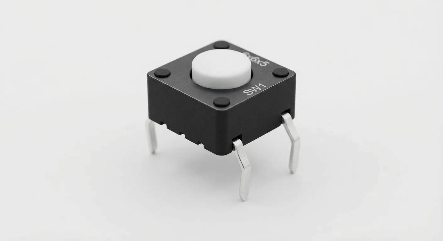
- Reviewed against the technical references below. Not compiled for an ESP32 or tested on hardware in this update. The approved product-style illustration identifies the family; follow documented terminal labels and the logical wiring diagram, not its rendered pin positions.
Overview
A common four-leg tactile button has two electrical contacts, each brought out to two legs. Pressing joins the two contacts. Choosing two legs already in the same group makes the circuit look permanently pressed.
Disconnect power and label your verified groups A1/A2 and B1/B2. Connect one A terminal to GPIO27 and one B terminal to GND. INPUT_PULLUP holds a released input HIGH; pressing closes it to LOW. The logical diagram is not a promise about every switch’s physical orientation.
Technical Specifications
Arduino library: No additional library; Arduino-ESP32 GPIO and millis
| Specification | Value | Why it matters |
|---|---|---|
| Switch assumption | Momentary, normally open | Latching and illuminated variants differ. |
| Terminal groups | A1/A2 joined; B1/B2 joined | Verify which physical legs form each group with power off. |
| Released state | HIGH with INPUT_PULLUP | An unconnected INPUT is not a reliable LOW. |
| Pressed state | LOW | The contact grounds the input; it does not apply a supply voltage. |
| Debounce window | 30 ms starting value | A software example, not a measured specification; tune for the actual switch. |
Pinout
- A1 / A2 (verified group) First contact One A terminal → GPIO27 Both A legs are electrically the same node; these labels are assigned after continuity checking.
- B1 / B2 (verified group) Second contact One B terminal → ESP32 GND Leave duplicate legs unused or in the same intended node; avoid breadboard shorts.
- Internal pull-up Defined released state pinMode(27, INPUT_PULLUP) Classic ESP32 GPIO27 supports pull-up; input-only GPIO34–39 do not have internal pulls.
Wiring Diagram
One verified A terminal to GPIO27 and one verified B terminal to GND. The sketch enables INPUT_PULLUP; released is HIGH and pressed is LOW.
| Component terminal | ESP32 / circuit connection | Purpose and qualification |
|---|---|---|
| A1 / A2 (verified group) | One A terminal → GPIO27 | Both A legs are electrically the same node; these labels are assigned after continuity checking. |
| B1 / B2 (verified group) | One B terminal → ESP32 GND | Leave duplicate legs unused or in the same intended node; avoid breadboard shorts. |
| Internal pull-up | pinMode(27, INPUT_PULLUP) | Classic ESP32 GPIO27 supports pull-up; input-only GPIO34–39 do not have internal pulls. |
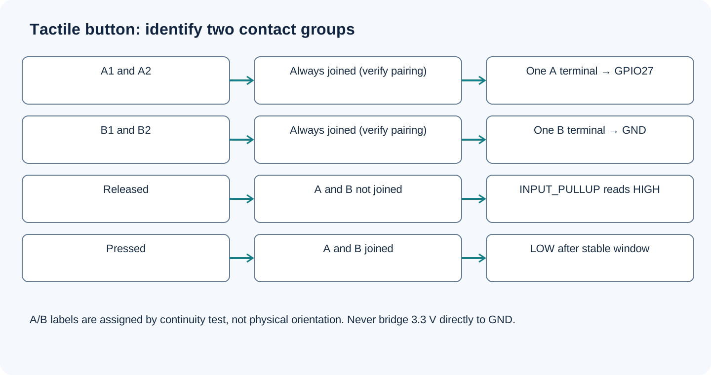
Open wiring diagram at full size (new tab)
-
1
Disconnect USB. Find the two pairs that are connected without pressing; pressing must join the groups.
-
2
Place the switch across separate breadboard nodes, often across the center gap when its actual geometry permits. Recheck continuity after insertion.
-
3
Connect one terminal from each different group as shown; do not bridge 3.3 V directly to GND.
-
4
Upload the stable-state sketch, then try slow and fast presses. Use actual contacts to tune the starting debounce window.
Wiring and matching Arduino code
Debounced button state
One verified A terminal to GPIO27 and one verified B terminal to GND. The sketch enables INPUT_PULLUP; released is HIGH and pressed is LOW.
tactile_push_button_esp32.ino
#include <Arduino.h>
constexpr uint8_t CONTACT_PIN = 27;
constexpr uint32_t DEBOUNCE_MS = 30; // Starting value; adjust for actual contacts.
int lastRaw = HIGH;
int stableState = -1;
uint32_t changedAt = 0;
void setup() {
  Serial.begin(115200);
  pinMode(CONTACT_PIN, INPUT_PULLUP);
  lastRaw = digitalRead(CONTACT_PIN);
  changedAt = millis();
}
void loop() {
  int raw = digitalRead(CONTACT_PIN);
  uint32_t now = millis();
  if (raw != lastRaw) { lastRaw = raw; changedAt = now; }
  if (now - changedAt >= DEBOUNCE_MS && raw != stableState) {
    stableState = raw;
    Serial.println(stableState == LOW ? "PRESSED" : "RELEASED");
  }
  delay(1);
}
A held button produces one state message, not repeated press events. The first report waits for stability. Count press edges only on accepted HIGH-to-LOW transitions if you later add a counter.
Expected Output
At 115200 baud, expect RELEASED when untouched and PRESSED when held, after the stable window. A four-leg switch wired across two permanently joined legs reads pressed even when untouched. Fast transitions shorter than the debounce window are intentionally ignored.
How it works
Contact bounce can produce several raw changes from one movement. Restarting the stability timer on each change avoids accepting those intermediate states. The duplicate legs are mechanical conveniences, not four independent inputs. Verify pairing rather than relying on an image or a same-side rule.
Troubleshooting
| Problem | Possible cause | Solution |
|---|---|---|
| Always PRESSED | Both chosen legs are in the same group or breadboard rows are shorted. | Unplug USB, identify pairs and recheck the inserted circuit with a meter. |
| Random RELEASED/PRESSED | Wrong GPIO, missing INPUT_PULLUP or loose connection. | Use GPIO27 with the matching sketch, common ground and the verified contact groups. |
| One press becomes several actions | Raw reads used as events or debounce bypassed. | Use accepted stable transitions; count only HIGH-to-LOW edges, not every loop while LOW. |
Where you use it
- Menu button
- LED control input
- Mode selection with debounced edges
Continue learning
Related projects
FAQ
In the assumed switch, each of its two electrical contacts has two legs. Confirm the actual pairing with the datasheet or continuity.
This INPUT_PULLUP circuit connects the switch to GND. A pull-down circuit is different; do not mix their wiring and logic.
GPIO27 can use INPUT_PULLUP for this short-wire example. An external pull resistor may be appropriate for a different pin or noisy/long wiring; choose it for the circuit.
Technical references
- Omron B3F manufacturer datasheet (RS-hosted copy) — Example contact arrangement and model-specific ratings; do not assume the unidentified switch is a B3F or transfer its minimum-load rating.
- Espressif GPIO API — Pull-up mode, pin restrictions and digitalRead.
- Arduino Debounce example — Stable-state timing using millis; debounce must suit actual contacts.
Downloads
Official manufacturer PDF for teachers and advanced builders.
No separate datasheet is needed for this beginner guide.