
Plain-English Overview
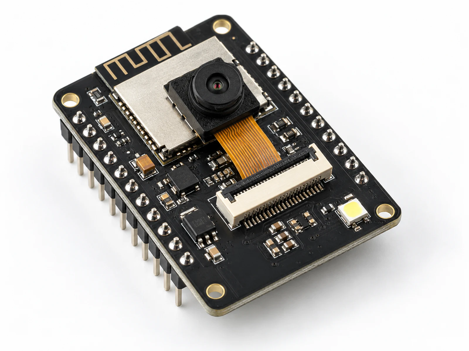
The ESP32-CAM is an ESP32 board with a tiny camera already connected to it. Instead of wiring every camera signal yourself, you use the board's fixed AI-Thinker pin map and write code with the built-in esp_camera driver.
It is different from a normal ESP32 DevKit because it usually does not have a USB port. You program it with an FTDI or CP2102 USB-to-serial adapter, ground IO0 only while uploading, then disconnect IO0 so the sketch can run.
The board is a low-voltage learning module, but cameras create privacy responsibilities. Use it only with consent, keep examples local by default, and do not present it as a professional security system.
Where You Use It
- Local image capture demos
- ESP32-CAM snapshot servers
- Classroom camera pinout lessons
- Local QR scanning projects
- Bounded computer-vision experiments
- Privacy and consent discussions
Quick Facts
- Board profile AI-Thinker ESP32-CAM
- Camera OV2640
- Programming FTDI serial adapter
- Boot mode IO0 to GND for upload only
- Power Stable 5 V supply
- Library esp_camera.h
How It Works
The AI-Thinker ESP32-CAM routes the OV2640 camera signals to fixed ESP32 GPIOs on the board. Firmware fills a camera_config_t structure with that pin map, selects a conservative frame size and JPEG quality, and calls esp_camera_init(). A project can then request a frame with esp_camera_fb_get(), use or serve the image, and return the frame buffer with esp_camera_fb_return().
Programming uses the ESP32 UART bootloader. IO0 grounded at reset selects upload mode. IO0 disconnected or high at reset lets the uploaded sketch run. That one jumper explains many upload and 'sketch will not start' problems.
Camera capture and Wi-Fi both raise current demand. If the 5 V source or wiring is weak, the board may reset or report camera initialization errors even when the code and pin map are correct.
Technical Specifications
Arduino library: Arduino ESP32 core esp_camera.h camera driver
| Specification | Value | Why it matters |
|---|---|---|
| Board variant | AI-Thinker ESP32-CAM | The pinout below is for the AI-Thinker profile used by the repository camera projects. |
| Camera sensor | OV2640 | The camera is already connected to the ESP32 on the module. |
| Logic level | 3.3 V GPIO | Do not drive ESP32 signal pins with 5 V logic. |
| Power input | 5 V board input | Use a stable 5 V source; weak FTDI adapters often brown out. |
| Recommended current headroom | 500 mA minimum, 1 A practical bench supply | Wi-Fi and frame capture create current spikes. |
| Programming mode | IO0 grounded at reset | Selects UART bootloader mode for flashing. |
| Normal run mode | IO0 disconnected from GND | Allows the uploaded sketch to boot normally. |
| PSRAM | Common on AI-Thinker boards; verify at runtime | Larger frame sizes require PSRAM and fail if allocation is unavailable. |
| Arduino board profile | AI Thinker ESP32-CAM | Use the matching board profile in Arduino-ESP32. |
| Supply in this build | 5 V AI-Thinker board input | AI-Thinker profile used by this page; camera driver documentation does not establish every clone board power rating. |
| GPIO signal level | 3.3 V GPIO / UART | AI-Thinker profile used by this page; camera driver documentation does not establish every clone board power rating. |
| Protection / level shifting | Use 3.3 V UART logic even when the board is powered at 5 V; verify the exact board schematic. | AI-Thinker profile used by this page; camera driver documentation does not establish every clone board power rating. |
Pinout
- 5V Power input Stable 5 V supply Use enough current headroom for Wi-Fi and camera capture.
- GND Ground FTDI GND and supply GND All power and serial connections share ground.
- U0R / RX0 UART receive FTDI TX Cross TX from the adapter to RX on the board.
- U0T / TX0 UART transmit FTDI RX Cross RX from the adapter to TX on the board.
- IO0 Boot strap GND only during upload Disconnect from GND after flashing so the sketch runs.
- PWDN Camera power-down GPIO32 AI-Thinker camera control pin.
- RESET Camera reset -1 / not connected The AI-Thinker profile leaves camera reset unconnected.
- XCLK Camera clock GPIO0 Part of the fixed camera map; avoid extra loads.
- SIOD Camera I2C data GPIO26 OV2640 control bus SDA.
- SIOC Camera I2C clock GPIO27 OV2640 control bus SCL.
- VSYNC Camera sync GPIO25 Fixed AI-Thinker sync pin.
- HREF Camera sync GPIO23 Fixed AI-Thinker sync pin.
- PCLK Camera pixel clock GPIO22 Fixed AI-Thinker pixel clock.
- Y9 Camera data GPIO35 Fixed OV2640 data line.
- Y8 Camera data GPIO34 Fixed OV2640 data line.
- Y7 Camera data GPIO39 Fixed OV2640 data line.
- Y6 Camera data GPIO36 Fixed OV2640 data line.
- Y5 Camera data GPIO21 Fixed OV2640 data line.
- Y4 Camera data GPIO19 Fixed OV2640 data line.
- Y3 Camera data GPIO18 Fixed OV2640 data line.
- Y2 Camera data GPIO5 Fixed OV2640 data line.
- Flash LED Illumination/status GPIO4 on common AI-Thinker boards Confirm clone-board wiring before relying on this LED.
Wiring Diagram
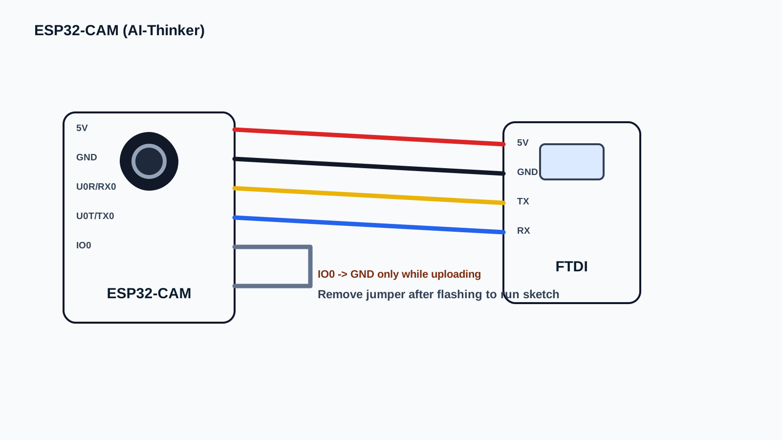
Programming mode and normal run mode use the same 5 V, GND, and crossed TX/RX wiring. The only difference is IO0: connect IO0 to GND while uploading, then disconnect IO0 from GND and reset the board to run the sketch. Use an adapter with 3.3 V UART logic. A 5 V power output label does not establish its TX voltage. Use one board supply and common ground; do not join independent power outputs.
-
1
Unplug the 5 V supply and USB-to-serial adapter before rewiring.
-
2
Connect adapter GND to ESP32-CAM GND.
-
3
Connect a stable 5 V supply to ESP32-CAM 5V.
-
4
Connect adapter TX to ESP32-CAM U0R/RX0.
-
5
Connect adapter RX to ESP32-CAM U0T/TX0.
-
6
For upload only, connect IO0 to GND and reset the board.
-
7
After upload, remove the IO0-to-GND jumper and reset the board for normal sketch execution.
Code Examples
Arduino-ESP32 3.x: select AI Thinker ESP32-CAM with OV2640 and the fixed pin map below. The bundled esp_camera.h driver is used; no separate camera library or server is required. This sketch captures JPEG frames and reports their sizes over Serial, not a video stream.
#include <Arduino.h>
#include "esp_camera.h"

#define PWDN_GPIO_NUM     32
#define RESET_GPIO_NUM    -1
#define XCLK_GPIO_NUM      0
#define SIOD_GPIO_NUM     26
#define SIOC_GPIO_NUM     27
#define Y9_GPIO_NUM       35
#define Y8_GPIO_NUM       34
#define Y7_GPIO_NUM       39
#define Y6_GPIO_NUM       36
#define Y5_GPIO_NUM       21
#define Y4_GPIO_NUM       19
#define Y3_GPIO_NUM       18
#define Y2_GPIO_NUM        5
#define VSYNC_GPIO_NUM    25
#define HREF_GPIO_NUM     23
#define PCLK_GPIO_NUM     22

void setup() {
  Serial.begin(115200);

  camera_config_t config = {};
  config.ledc_channel = LEDC_CHANNEL_0;
  config.ledc_timer = LEDC_TIMER_0;
  config.pin_d0 = Y2_GPIO_NUM;
  config.pin_d1 = Y3_GPIO_NUM;
  config.pin_d2 = Y4_GPIO_NUM;
  config.pin_d3 = Y5_GPIO_NUM;
  config.pin_d4 = Y6_GPIO_NUM;
  config.pin_d5 = Y7_GPIO_NUM;
  config.pin_d6 = Y8_GPIO_NUM;
  config.pin_d7 = Y9_GPIO_NUM;
  config.pin_xclk = XCLK_GPIO_NUM;
  config.pin_pclk = PCLK_GPIO_NUM;
  config.pin_vsync = VSYNC_GPIO_NUM;
  config.pin_href = HREF_GPIO_NUM;
  config.pin_sccb_sda = SIOD_GPIO_NUM;
  config.pin_sccb_scl = SIOC_GPIO_NUM;
  config.pin_pwdn = PWDN_GPIO_NUM;
  config.pin_reset = RESET_GPIO_NUM;
  config.xclk_freq_hz = 20000000;
  config.pixel_format = PIXFORMAT_JPEG;
  config.frame_size = psramFound() ? FRAMESIZE_VGA : FRAMESIZE_QVGA;
  config.jpeg_quality = 12;
  config.fb_count = psramFound() ? 2 : 1;
  config.fb_location = psramFound() ? CAMERA_FB_IN_PSRAM : CAMERA_FB_IN_DRAM;
  config.grab_mode = CAMERA_GRAB_WHEN_EMPTY;

  esp_err_t err = esp_camera_init(&config);
  if (err != ESP_OK) {
    Serial.printf("Camera init failed: 0x%x\n", err);
    Serial.println("Check AI-Thinker board profile, 5 V power, ribbon cable, and PSRAM/frame settings.");
    while (true) delay(1000);
  }

  Serial.println("ESP32-CAM initialized with AI-Thinker pin map.");
}

void loop() {
  camera_fb_t *frame = esp_camera_fb_get();
  if (!frame) {
    Serial.println("Capture failed. Check power and camera connection.");
  } else {
    Serial.printf("JPEG frame: %u x %u, %u bytes\n",
                  (unsigned)frame->width, (unsigned)frame->height, (unsigned)frame->len);
    esp_camera_fb_return(frame);
  }
  delay(1000);
}
Assumes a classic AI-Thinker ESP32-CAM with OV2640, Arduino-ESP32 3.x and the listed camera pin map. Select the matching board profile and enable PSRAM when the board has it; the sketch chooses VGA/two buffers with detected PSRAM, otherwise QVGA/one buffer. Use stable 5 V board power and a USB-to-UART bridge with 3.3 V TX/RX logic, regardless of its power-pin label. Share adapter/board ground; do not tie two separate 5 V sources together. Each acquired frame is returned to the driver before the next capture. Documentation reviewed; this revision has not been compiled or tested on physical hardware.
Expected Output
At 115200 baud, initialization is followed by JPEG frame dimensions and byte counts about once per second. Sizes vary with the scene; this is expected behavior, not a recorded measurement. An initialization error stops the sketch; a capture error is reported and retried on the next loop. Successful initialization does not verify all power, image-quality or network behavior.
Common Mistakes
- Leaving IO0 grounded after flashing, which keeps the board in bootloader mode.
- Connecting FTDI TX-to-TX and RX-to-RX instead of crossing TX/RX.
- Powering the camera from a weak FTDI adapter or unstable USB port.
- Choosing a frame size that needs PSRAM when PSRAM is not available.
- Treating a local classroom demo as a professional security camera.
- Pointing the camera at people or private spaces without consent.
Troubleshooting
| Problem | Possible cause | Solution |
|---|---|---|
| Upload does not start | IO0 is not grounded during reset or TX/RX are not crossed. | Ground IO0, reset, confirm adapter TX goes to U0R and adapter RX goes to U0T, then upload again. |
| Upload succeeds but sketch will not run | IO0 is still tied to GND after flashing. | Remove the IO0-to-GND jumper and reset the board. |
| Camera init failed | Wrong board profile, loose ribbon cable, unsupported frame size, or weak power. | Select AI Thinker ESP32-CAM, reseat the camera ribbon gently, start with QVGA/VGA, and use stable 5 V power. |
| Random resets or brownout messages | Wi-Fi or camera capture current spikes exceed the supply or wiring capability. | Use a dedicated 5 V supply with more current headroom and short power wires; add a bulk capacitor only as practical filtering, not as a universal fix. |
| Large frames fail | PSRAM is missing, disabled, or not detected. | Check psramFound(), use the AI Thinker profile, and reduce frame size when PSRAM is unavailable. |
Related Guides
Related Projects
FAQ
It is an ESP32 board with an OV2640 camera connected through a fixed AI-Thinker pin map.
Connect IO0 to GND only during upload, then disconnect it from GND before resetting the board to run the sketch.
The most common cause is weak 5 V power during Wi-Fi or camera capture current spikes.
Check IO0-to-GND for upload mode and cross the serial lines: adapter TX to board U0R, adapter RX to board U0T.
No. Treat it as an educational local camera board; do not expose example projects to the public internet.
IO0 is a boot strap pin. Grounded at reset means programming mode; disconnected or high at reset means normal sketch execution.
PSRAM is extra memory on many ESP32-CAM boards. It helps larger camera frames fit in memory.
The board is low voltage; the main concern is privacy and consent. Keep the camera visible and use it only with awareness of people nearby.
Check stable 5 V power, remove IO0 from GND after flashing, and confirm the camera is not aimed at private spaces.
Use it to teach boot modes, pin maps, local web servers, and privacy-by-design in one contained lab.
Have students record upload wiring, normal-run wiring, selected frame size, and how they handled consent.
Run the init-check sketch, then capture one local frame before adding any larger project logic.
Add a visible status LED or physical lens cover and keep all access on the local network.
Only IO0 changes: grounded for upload, disconnected from GND for normal run.
The adapter transmits into the board receiver, and the board transmits back into the adapter receiver.
No. It captures JPEG frames and reports their dimensions and byte counts over Serial. A server and viewing interface are separate steps, and readable image quality must be checked on actual hardware.
Review, Testing, and References
Author: Abdul Mubeen and the ESP32 Engine editorial team. Last updated: 2026-10-08. Reviewed: wiring, code, beginner safety, and ESP32 compatibility. Educational level: Intermediate.
Use this component page as an educational starting point. Check official documentation before using the part in production, high-current, outdoor, battery, or safety-critical hardware.
Driver reference
Espressif camera driver reference used by Arduino ESP32 camera examples.
Open Espressif camera driver reference