
Before you start
- Board and software
- Classic ESP32-WROOM-32/32E DevKit with the specified unused GPIOs exposed; Arduino IDE 2.x and Arduino-ESP32 3.x. Other families require their own pin map. Serial Monitor: 115200 baud. No extra library.
- Supported hardware
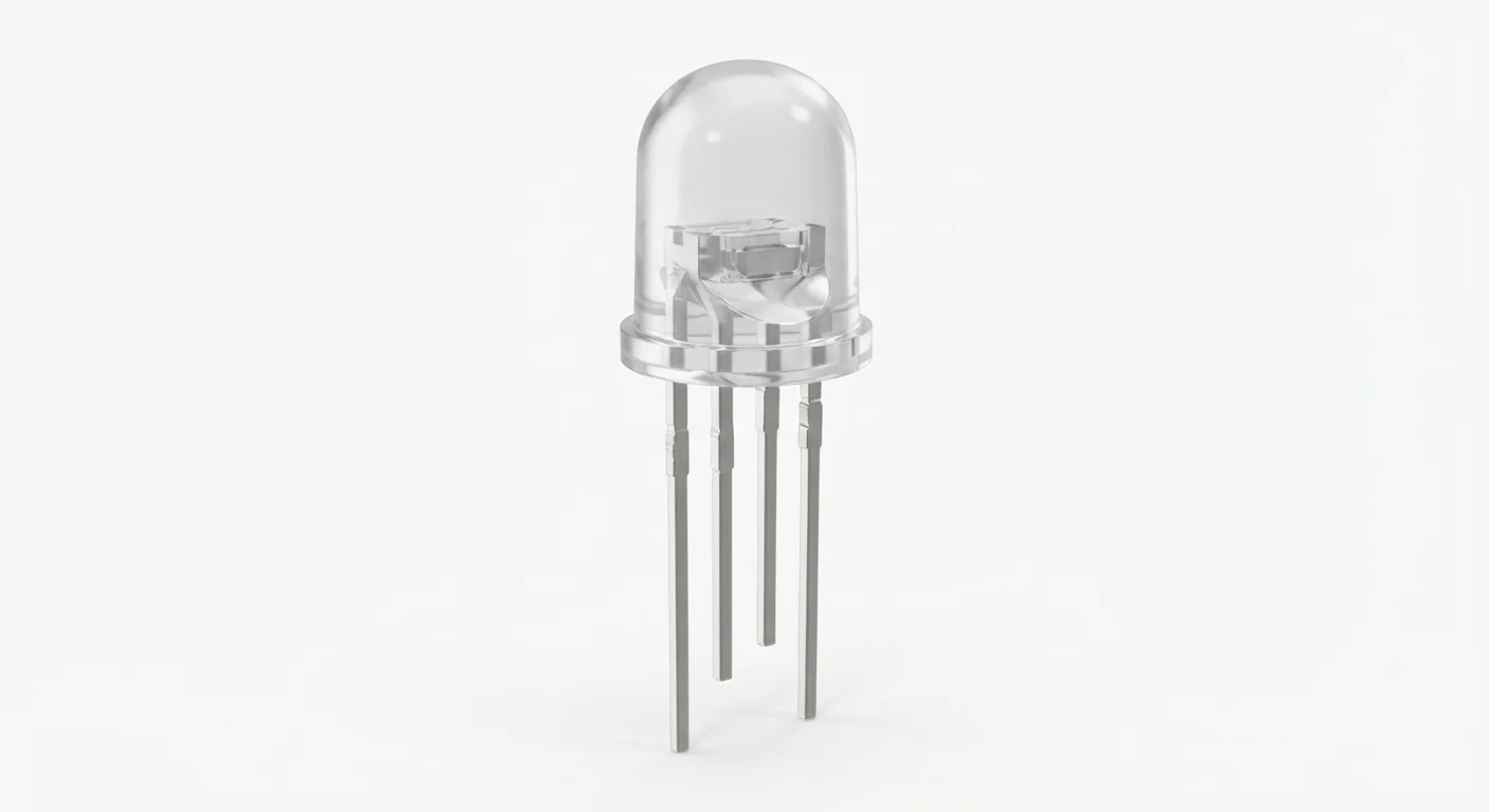
- A documented bare four-lead common-cathode RGB LED whose channels tolerate the resistor-limited 3.3 V test. Confirm actual R/G/B/common leads before wiring. The illustration cannot establish common-terminal type or package size.
- Prerequisites and parts
- IDE setup, Blink, RGB LED and three known 470 ohm / 0.25 W resistors; breadboard, wires and part documentation.
- Expected result
- Red, green and blue channels are requested in turn for one second, with an all-off pause. Blue/green brightness at 3.3 V is not guaranteed; it depends on actual forward voltage.
- Verification limits
- Documentation and automated content/browser checks only in this update. No ESP32 compilation or physical hardware testing. The approved image depicts a component family; it does not authenticate a model, rating or terminal order.
Overview
Three LED junctions share one terminal. Common cathode joins their negative terminals; common anode joins their positive terminals. This example supports common cathode only. It is not a WS2812/addressable LED.
Find the actual circuit symbol and lead order in the datasheet. Do not treat the longest lead, the artwork or another LED's pin order as proof. Kingbright's RGB datasheet is a reference example, not a match to this illustration.
Technical Specifications
Arduino library: Arduino-ESP32 3.x; no additional library
| Specification | Value | Why it matters |
|---|---|---|
| Common terminal | Common cathode for example | Other types need a different circuit and inverted logic. |
| Color resistors | Three separate 470 ohm resistors | Limits each independent junction; no shared common-terminal resistor. |
| Voltage headroom | Part-dependent | Some blue/green channels need more than a 3.3 V rail for useful brightness. |
| Supply in this example | No separate rail in this common-cathode example; each GPIO drives a color through 470 ohms. | Applies only to the supported hardware assumptions above. |
| ESP32 signal compatibility | GPIO25/26/27 are 3.3 V outputs; HIGH turns the selected channel on. | Applies only to the supported hardware assumptions above. |
| Required protection | One resistor per channel. Never connect a common anode to 5 V and return its channels directly to ESP32 pins. | Applies only to the supported hardware assumptions above. |
Pinout
- Common cathode Verified by the real part datasheet; no physical lead order assumed. ESP32 GND Verified by the real part datasheet; no physical lead order assumed.
- Red anode One resistor for this channel. GPIO25 through 470 ohms One resistor for this channel.
- Green anode One resistor for this channel. GPIO26 through 470 ohms One resistor for this channel.
- Blue anode One resistor for this channel. GPIO27 through 470 ohms One resistor for this channel.
Wiring Diagram
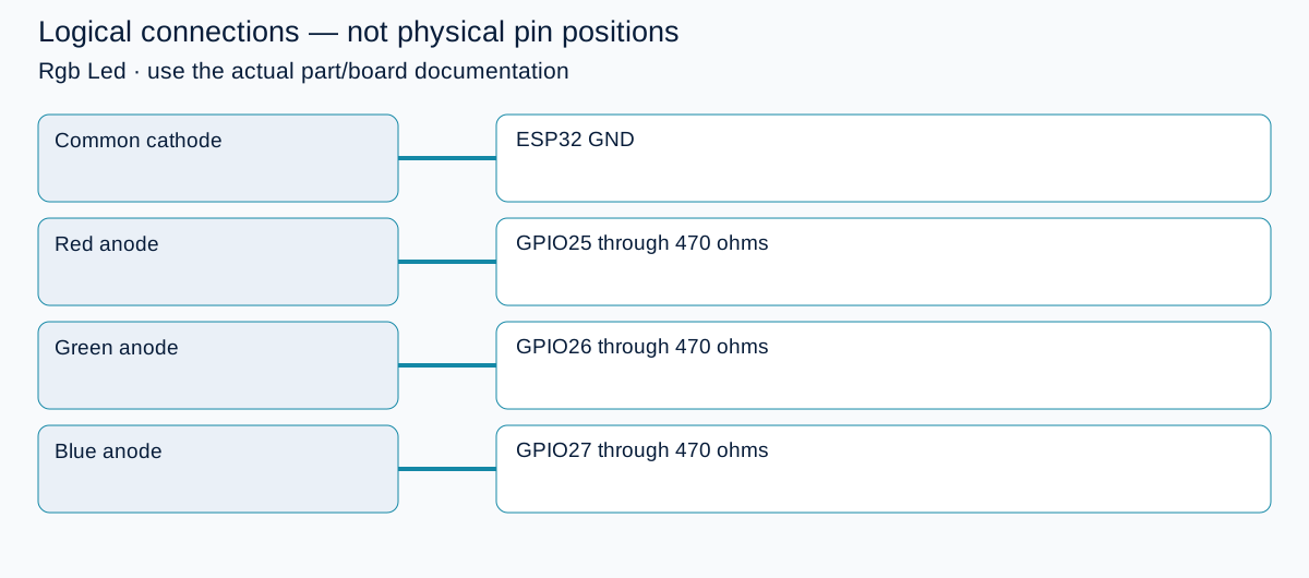
Verified common cathode → GND; R/G/B anodes → separate 470 ohm resistors → GPIO25/26/27.
| Identified terminal | Connection | Qualification |
|---|---|---|
| Common cathode | ESP32 GND | Verified by the real part datasheet; no physical lead order assumed. |
| Red anode | GPIO25 through 470 ohms | One resistor for this channel. |
| Green anode | GPIO26 through 470 ohms | One resistor for this channel. |
| Blue anode | GPIO27 through 470 ohms | One resistor for this channel. |
Open wiring diagram at full size (new tab)
-
1
Power off and identify common-terminal type and all four leads.
-
2
Wire one resistor in each color path; connect common cathode to GND.
-
3
Upload, then compare Serial channel labels with the actual emitted colors.
Wiring and matching Arduino code
One color at a time
Verified common cathode → GND; R/G/B anodes → separate 470 ohm resistors → GPIO25/26/27.
rgb_led_esp32.ino
#include <Arduino.h>
constexpr uint8_t RED_PIN = 25, GREEN_PIN = 26, BLUE_PIN = 27;
const uint8_t pins[] = {RED_PIN, GREEN_PIN, BLUE_PIN};
const char* names[] = {"RED", "GREEN", "BLUE"};
void allOff() { for (uint8_t pin : pins) digitalWrite(pin, LOW); }
void setup() {
  Serial.begin(115200);
  for (uint8_t pin : pins) { pinMode(pin, OUTPUT); digitalWrite(pin, LOW); }
}
void loop() {
  for (uint8_t i = 0; i < 3; ++i) {
    allOff();
    digitalWrite(pins[i], HIGH);
    Serial.println(names[i]);
    delay(1000);
    allOff();
    delay(300);
  }
}
Common-cathode only. Begin with one active color to identify leads; this is not calibrated color mixing or a brightness measurement.
Expected Output
Red, green and blue channels are requested in turn for one second, with an all-off pause. Blue/green brightness at 3.3 V is not guaranteed; it depends on actual forward voltage.
How it works
Each GPIO controls one LED junction. Resistor values and different forward voltages affect balance, so equal drive does not imply equal brightness. This simple digital test avoids PWM setup. The linked controller introduces PWM using its own hardware assumptions. If higher voltage is needed, design a separate transistor/driver interface rather than feeding 5 V into ESP32 GPIO.
Troubleshooting
| Problem | Possible cause | Solution |
|---|---|---|
| Colors do not match Serial labels | Lead order differs from the assumed assignment. | Power off and remap leads from the actual datasheet. |
| All colors stay dark | Common-anode device, incorrect common wire or unsuitable voltage. | Identify topology first; do not randomly attach a supply rail. |
| Only red is bright | Blue/green forward voltage or resistor/part differences. | Check actual forward-voltage data. Do not remove the resistors to force brightness. |
Where you use it
- Three-state indicator
- Color pattern learning
- RGB PWM project preparation
Continue learning
Related projects
FAQ
No. A 3.3 V common-anode circuit uses GPIO sinking with LOW meaning on, and needs verified pin/current limits. The provided code and wiring are common-cathode only.
No. Four-lead analog RGB LEDs need three separate color outputs. WS2812-style parts use a different power and data interface.
Technical references
- Espressif GPIO API — Pin modes and digital output on Arduino-ESP32.
- Kingbright RGB LED datasheet — Example electrical characteristics and package circuit; not identification of the generic illustration.