
Before you start
- Board and software
- Classic ESP32-WROOM-32/32E DevKit with the listed GPIOs exposed and unused. Arduino IDE 2.x; esp32 by Espressif Systems 3.3.2 (review baseline, not a latest-release claim). Select the documented board or ESP32 Dev Module for a generic WROOM board. Other families need their own pin map. Serial Monitor: 115200 baud.
- Supported hardware
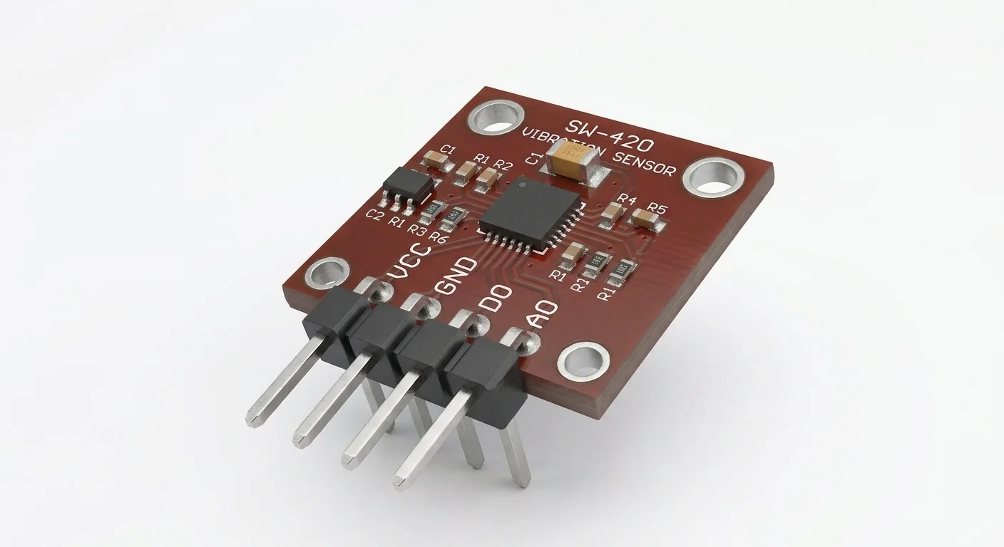
- Worked reference: Seeed Grove Vibration Sensor (SW-420), documented for 3.3 V, quiet HIGH and vibration LOW. Generic modules may invert polarity or have different pull-ups. The approved SW-420-labelled illustration is not the Grove board or a verified schematic; its AO label is not evidence of an analog acceleration output.
- Prerequisites and parts
- IDE setup and digital-input lesson. The documented Seeed reference or a carrier proven electrically equivalent for this wiring/polarity, short wires and GPIO27 free. Check the actual connector labels and signal voltage. No 5 V rail or external load required.
- Libraries
- Arduino-ESP32 3.3.2 GPIO interrupts; no sensor library.
- Expected result
- Serial reports accumulated falling edges once per second. Multiple pulses may follow one disturbance; counts do not measure force or displacement.
- Verification status
- Documentation and source review only. Not compiled or tested on hardware. The approved product-style illustration identifies a family, not a verified physical pin layout or manufacturer-authenticated board. Follow the logical diagram and documentation for your actual part.
Overview
SW-420 is a mechanical vibration-sensitive switch used with a comparator to create short digital changes. A trimmer changes the comparator threshold. It does not turn the switch into an accelerometer or establish a distance, force or vibration spectrum.
The supported Seeed circuit is HIGH while quiet and briefly LOW when disturbed. This example captures falling edges because a slow polling sketch can miss a pulse. Verify the actual carrier’s supply, output pull-up and quiet/active states before using this code on a different board. A four-pin illustration is not evidence that the documented Grove reference has an AO connector.
Technical Specifications
Arduino library: Arduino-ESP32 3.3.2 built-in GPIO interrupts; no extra library.
| Specification | Value | Why it matters |
|---|---|---|
| Worked hardware | Seeed Grove SW-420 at 3.3 V | Generic artwork does not establish equivalence. |
| Output meaning | Short HIGH-to-LOW transitions | Mechanical bounce and comparator chatter can create multiple events. |
| GPIO27 interrupt | FALLING; count in ISR | No printing or delays inside the interrupt. |
| Reported quantity | Edges per reporting interval | Not acceleration, force or distinct-impact count. |
Pinout
- Reference VCC Supply ESP32 3.3 V Only documented 3.3 V operation.
- Reference GND Reference ESP32 GND Check connector orientation with power off.
- Reference SIG / digital output Input GPIO27 Quiet HIGH/event LOW; 3.3 V signal.
- NC / unused connector position Unused Leave disconnected Use exact reference pin labels, not header order.
- AO on a different module Unsupported Leave disconnected Illustration does not establish its meaning or voltage.
Wiring Diagram
Documented reference VCC → 3.3 V, GND → GND, SIG → GPIO27. Leave unused pins disconnected. FALLING edges represent the reference LOW pulses.
| Component terminal | ESP32 / circuit connection | Purpose and qualification |
|---|---|---|
| Reference VCC | ESP32 3.3 V | Only documented 3.3 V operation. |
| Reference GND | ESP32 GND | Check connector orientation with power off. |
| Reference SIG / digital output | GPIO27 | Quiet HIGH/event LOW; 3.3 V signal. |
| NC / unused connector position | Leave disconnected | Use exact reference pin labels, not header order. |
| AO on a different module | Leave disconnected | Illustration does not establish its meaning or voltage. |
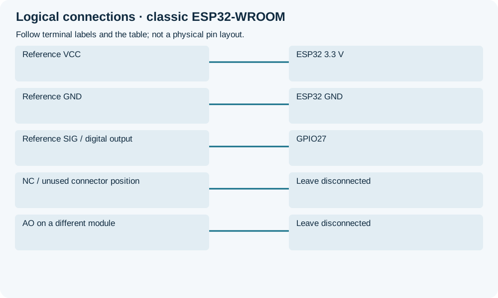
Open wiring diagram at full size (new tab)
-
1
Disconnect power; verify actual supply, connector pin map and comparator/output pull-up rail. For an unknown module, establish equivalence before connecting.
-
2
Upload and open 115200 baud. Let the assembly sit still, then gently disturb the supporting surface; do not strike the electronics.
-
3
Adjust the actual reference trimmer gradually if needed. Compare quiet/event behavior and keep pulse counts separate from impact counts.
Wiring and matching Arduino code
Count brief digital pulses
Documented reference VCC → 3.3 V, GND → GND, SIG → GPIO27. Leave unused pins disconnected. FALLING edges represent the reference LOW pulses.
sw420_vibration_sensor.ino
#include <Arduino.h>
constexpr uint8_t VIBRATION_PIN = 27;
volatile uint32_t edgeCount = 0;
portMUX_TYPE counterMux = portMUX_INITIALIZER_UNLOCKED;
uint32_t lastReport = 0;
void ARDUINO_ISR_ATTR onFallingEdge() {
  portENTER_CRITICAL_ISR(&counterMux);
  ++edgeCount;
  portEXIT_CRITICAL_ISR(&counterMux);
}
void setup() {
  Serial.begin(115200);
  pinMode(VIBRATION_PIN, INPUT);
  attachInterrupt(digitalPinToInterrupt(VIBRATION_PIN), onFallingEdge, FALLING);
  Serial.println("Reference: quiet HIGH, disturbance LOW; counts are edges.");
}
void loop() {
  const uint32_t now = millis();
  if (now - lastReport >= 1000) {
    lastReport = now;
    portENTER_CRITICAL(&counterMux);
    const uint32_t captured = edgeCount;
    edgeCount = 0;
    portEXIT_CRITICAL(&counterMux);
    Serial.printf("falling_edges=%lu level=%d\n",
                  static_cast<unsigned long>(captured), digitalRead(VIBRATION_PIN));
  }
  delay(1);
}
Critical sections protect a shared ISR counter; serial output occurs outside them. No universal debounce interval is asserted. Group pulses into application events only after observing the actual switch and deciding a suitable time window.
Expected Output
Quiet reference hardware should usually report HIGH and few/no edges. A disturbance can produce LOW pulses and multiple falling edges, even if the sampled level is HIGH by print time. These are expected behaviors for the stated circuit, not hardware measurements from this update.
How it works
In the Seeed circuit, mechanical contact changes move one comparator input relative to the trimmer reference. The comparator produces a pulse rather than a calibrated analog quantity. An interrupt records the transition and the loop reports the snapshot. Pulse grouping for a mailbox/knock detector is an application decision; one mechanical disturbance may contain several electrical edges.
Troubleshooting
| Problem | Possible cause | Solution |
|---|---|---|
| No counts despite a visible pulse | Wrong signal pin/polarity or GPIO map. | Verify output level safely against GND and the documented quiet/active states; a rising-active carrier requires a separately matched example. |
| Counts while untouched | Threshold too sensitive, contact chatter or noise. | Use short wires and adjust the documented trimmer; distinguish environmental movement from wiring noise. |
| Printed level HIGH but count nonzero | Short LOW pulses ended before the report. | That is why the ISR is used. Do not expect a once-per-second level sample to preserve pulse duration. |
| Many counts for one knock | Switch bounce/comparator chatter. | Do not call them impacts. Add a documented application grouping window only after observation. |
Where you use it
- Learning pulse capture with GPIO interrupts
- A relative disturbance indicator with verified sensitivity
Continue learning
FAQ
Not from the illustration or this digital reference circuit. Use a documented accelerometer when physical acceleration is required.
No. Check purchased module labels/schematic and output pull-ups. The logical diagram identifies connections, not a physical orientation.
Technical references
- Seeed Grove SW-420 documentation and schematic — 3.3 V option, quiet/event polarity and comparator operation for this reference only.
- Arduino-ESP32 3.3.2 GPIO implementation — Pinned attachInterrupt and GPIO APIs.
- Arduino-ESP32 3.3.2 HAL definitions — ISR placement attribute. Critical sections follow Espressif FreeRTOS spinlock guidance.
- Espressif ESP-IDF 5.5 FreeRTOS critical sections — Matched ISR/task portMUX critical sections on classic ESP32.