
Before you start
- Board and software
- Low-voltage bench setup as specified below. ESP32 is optional for passive exercises. Coded examples require classic ESP32-WROOM-32/32E DevKit, unused exposed pins, Arduino IDE 2.x and Arduino-ESP32 3.3.2 (review baseline, not a latest-release claim). Other families need their own pin map.
- Supported hardware
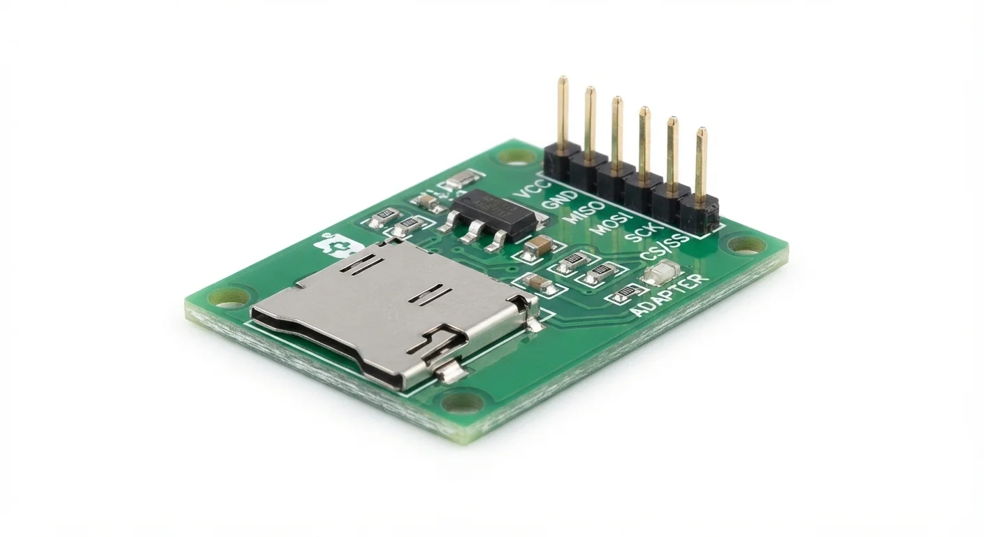
- Approved generic SD card adapter illustration; regulator and level shifting unverified. Worked reference: Adafruit MicroSD SPI/SDIO breakout 4682, a 3 V-only board, used in SPI mode.
- Prerequisites and parts
- Classic WROOM DevKit, documented reference breakout, spare FAT32 card prepared on a computer with /hello.txt and short wires. Back up data; power off before inserting/removing or rewiring.
- Libraries
- Arduino-ESP32 3.3.2 built-in SD, FS and SPI; no separately installed generic SD library.
- Expected result
- Serial prints up to 256 bytes of /hello.txt or a clear mount/file error; the sketch does not format or write the card.
- Verification status
- Documentation and source review only. Not compiled or tested on hardware. The approved product-style illustration identifies a family, not a verified physical pin layout or manufacturer-authenticated board. Follow the logical diagram and documentation for your actual part.
Overview
A microSD socket carrier exposes the card through SPI or another supported interface. A module marked 5V may include a regulator, level shifters, both or neither; the illustration cannot establish its circuit.
This example uses a documented 3 V-only reference and explicit SPI pins. Card power and signals stay in the 3.3 V domain. Other carriers can change labels, pull-ups and timing. The card must be formatted compatibly before the test; mounting is not formatting.
Technical Specifications
Arduino library: Built-in SD, FS and SPI — Arduino-ESP32 3.3.2
| Specification | Value | Why it matters |
|---|---|---|
| SPI assignment | SCK18, MISO19, MOSI23, CS27 | Unused exposed WROOM pins required. |
| Test clock | 1 MHz | Conservative starting value, not guaranteed performance. |
| Test file | /hello.txt on prepared FAT32 | Read only; at most 256 bytes printed. |
Pinout
- 3V Supply ESP32 3V3 Reference3Vonly.
- GND Reference ESP32 GND Common ground.
- CLK Clock GPIO18 SPI.
- SO Input GPIO19 Card output.
- SI Output GPIO23 Card input.
- CS Select GPIO27 Active LOW.
- Other pins Unused Leave disconnected SPI only.
Wiring Diagram
Reference3.3 V/GND, CLK18, SO19, SI23, CS27; other pins unconnected.
| Component terminal | ESP32 / circuit connection | Purpose and qualification |
|---|---|---|
| 3V | ESP32 3V3 | Reference3Vonly. |
| GND | ESP32 GND | Common ground. |
| CLK | GPIO18 | SPI. |
| SO | GPIO19 | Card output. |
| SI | GPIO23 | Card input. |
| CS | GPIO27 | Active LOW. |
| Other pins | Leave disconnected | SPI only. |
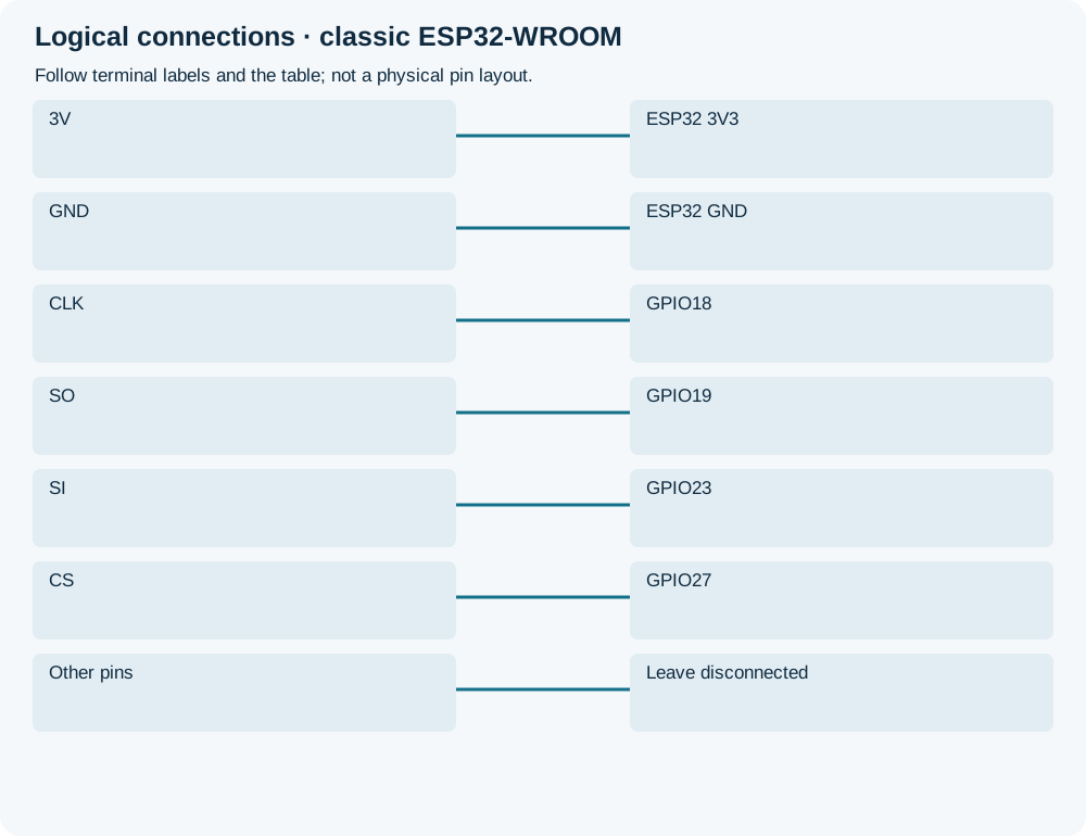
Open wiring diagram at full size (new tab)
-
1
Prepare a spare backed-up FAT32 card with hello.txt on a computer.
-
2
Power off, insert card and wire exact reference labels.
-
3
Upload and open Serial115200; inspect mount/file diagnostic before changing clock.
Wiring and matching Arduino code
Read a prepared text file without writing
Reference3.3 V/GND, CLK18, SO19, SI23, CS27; other pins unconnected.
microsd_card_module.ino
#include <Arduino.h>
#include <SPI.h>
#include <SD.h>
#include <FS.h>
constexpr uint8_t CARD_CS = 27;
void setup() {
  Serial.begin(115200);
  SPI.begin(18, 19, 23, CARD_CS);
  if (!SD.begin(CARD_CS, SPI, 1000000)) {
    Serial.println("SD mount failed: check power, wiring and prepared card"); return;
  }
  if (SD.cardType() == CARD_NONE) { Serial.println("No card detected"); SD.end(); return; }
  File file = SD.open("/hello.txt", FILE_READ);
  if (!file || file.isDirectory()) {
    Serial.println("Missing /hello.txt or not a file");
    if (file) file.close();
    SD.end(); return;
  }
  Serial.println("First up to 256 bytes of /hello.txt:");
  for (uint16_t count = 0; count < 256 && file.available(); ++count) {
    const int value = file.read();
    if (value < 0) { Serial.println("Read error"); break; }
    Serial.write(static_cast<uint8_t>(value));
  }
  Serial.println(); file.close(); SD.end();
}
void loop() { delay(1000); }
Pinned 3.3.2 SD.begin uses format_if_empty=false by default. This sketch reads once at startup; reset after changing a file with power removed. It does not prove sustained write performance or data integrity.
Expected Output
A supported prepared card should mount and print the first up to 256 bytes. A missing file is distinct from a failed mount. No automatic formatting, logging or filesystem repair occurs.
How it works
SPI assigns separate clock, input, output and chip-select pins; SO/MISO is from the card perspective. The ESP32 SD wrapper mounts the filesystem and opens one file read-only. Power interruptions during other applications writes can corrupt data; this simple reader is not a power-loss-safe logger.
Troubleshooting
| Problem | Possible cause | Solution |
|---|---|---|
| Mount failed | Wrong labels, supply/burst current, format or unsuitable carrier. | Check actual schematic, short wires and spare supported FAT32 card; do not autoformat valuable data. |
| File missing | Name/path differs or card prepared incorrectly. | Verify root hello.txt on computer, then power off before moving card. |
| Intermittent reads | Poor contact, long wires or marginal power. | Review power/decoupling and connections; do not assume faster clock fixes it. |
Where you use it
- Reading configuration or text from a prepared card
- Checking SPI wiring before building a logger
FAQ
Only after verifying its actual signal/level-shifting circuit; the label is insufficient.
Not in this example. Prepare a compatible card separately.
Technical references
- Adafruit 4682 pinouts — 3 V-only worked reference and SPI terminals.
- Pinned ESP32 SD header — begin parameters, default formatting disabled and card type.
- Pinned SPI API — Explicit pin assignment.