
Before you start
- Board and software
- Classic ESP32-WROOM-32/32E DevKit with these GPIOs exposed and unused. Arduino IDE 2.x; esp32 by Espressif Systems 3.x (API review baseline 3.3.2, not a latest-version claim). Select the exact board or ESP32 Dev Module for a generic WROOM board. Other ESP32 families need their own pin map. Serial Monitor: 115200 baud.
- Hardware assumption
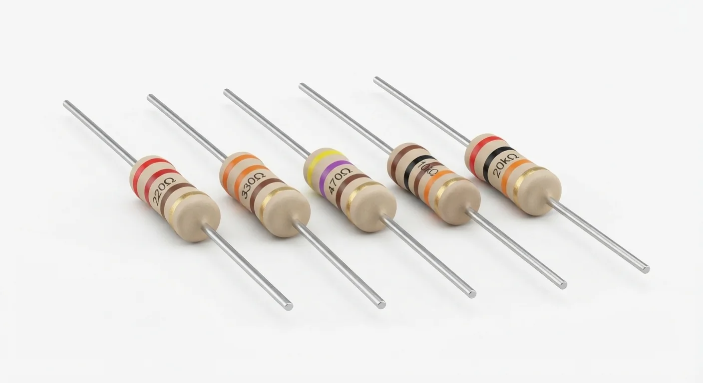
- Axial fixed resistors with manufacturer-documented resistance, tolerance and power rating. Image labels and colors are illustrative, not verified measurements. The example uses a known 470 ohm, 0.25 W resistor and a low-current indicator LED with documented polarity/current requirements.
- Prerequisites and parts
- First complete Arduino IDE setup and Blink. 470 ohm resistor, suitable LED, breadboard and wires; a multimeter and part documentation for value/rating checks.
- Expected result
- The external LED on GPIO25 blinks one second on, one second off; its brightness depends on the actual LED and circuit.
- Verification status
- Reviewed against the technical references below. Not compiled for an ESP32 or tested on hardware in this update. The approved product-style illustration identifies the family; follow documented terminal labels and the logical wiring diagram, not its rendered pin positions.
Overview
A resistor limits current or forms a divider/pull resistor with other parts. It has no preferred direction and no independent supply pin. A series resistor is essential for a bare indicator LED; it does not make a 5 V signal automatically safe for ESP32.
Read four bands as two significant digits, multiplier and tolerance; five bands add a third digit. The tolerance band often has extra spacing, but confirm ambiguous bands with a meter. Body size/color and this illustration do not prove wattage.
Technical Specifications
Arduino library: No additional library; Arduino GPIO output
| Specification | Value | Why it matters |
|---|---|---|
| Four-band 220 ohm example | Red, red, brown, gold = 22 × 10, ±5% | A teaching example, not a reading of the generated artwork. |
| Four-band 470 ohm example | Yellow, violet, brown, gold = 47 × 10, ±5% | Verify the actual resistor with a meter. |
| Four-band 10 kOhm example | Brown, black, orange, gold = 10 × 1000, ±5% | Useful pull-up value in suitable circuits; not universal. |
| Five-band 1 kOhm example | Brown, black, black, brown, brown = 100 × 10, ±1% | Three significant digits, then multiplier and tolerance. |
| LED resistor selection | R ≥ (supply − LED forward voltage) / target current | Illustrative 3.3 V, 2.0 V LED and 3 mA target gives at least 433 ohm; 470 ohm gives about 2.8 mA. Actual LED voltage varies. |
| Power rating | P = I²R = Vresistor²/R | That illustrative 470 ohm calculation dissipates about 3.6 mW. Use the documented 0.25 W part here; larger loads need derating and their own calculation. |
Pinout
- Resistor lead A Series current path GPIO25 An unpolarized resistor can be installed either way.
- Resistor lead B LED feed LED anode Either side of the LED may hold the series resistor; this example puts it on the anode side.
- LED cathode Return ESP32 GND Verify polarity from LED documentation/diode test, not a shortened lead.
Wiring Diagram
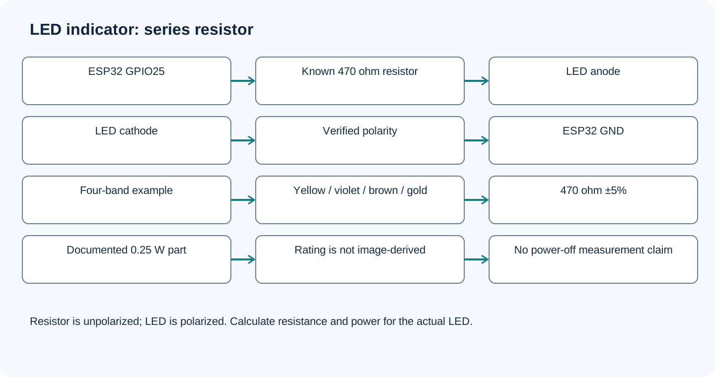
GPIO25 → known 470 ohm resistor → LED anode; LED cathode → GND. Use an external LED, not an assumed onboard GPIO2 LED.
| Component terminal | ESP32 / circuit connection | Purpose and qualification |
|---|---|---|
| Resistor lead A | GPIO25 | An unpolarized resistor can be installed either way. |
| Resistor lead B | LED anode | Either side of the LED may hold the series resistor; this example puts it on the anode side. |
| LED cathode | ESP32 GND | Verify polarity from LED documentation/diode test, not a shortened lead. |
Open wiring diagram at full size (new tab)
-
1
Unplug USB. Read the actual bands and verify the resistor value; measure isolated or lift one lead to avoid parallel circuit paths.
-
2
Confirm documented resistor wattage and LED polarity/current limits; calculate for your actual forward voltage and target current.
-
3
Connect the series circuit and upload the sketch. Never connect a bare LED directly across GPIO and ground.
-
4
Stop and check wiring/value if a part heats; this is only a small low-voltage indicator circuit.
Wiring and matching Arduino code
External LED with a series resistor
GPIO25 → known 470 ohm resistor → LED anode; LED cathode → GND. Use an external LED, not an assumed onboard GPIO2 LED.
through_hole_resistors_esp32.ino
#include <Arduino.h>
constexpr uint8_t LED_PIN = 25;
void setup() {
  pinMode(LED_PIN, OUTPUT);
  digitalWrite(LED_PIN, LOW);
}
void loop() {
  digitalWrite(LED_PIN, HIGH);
  delay(1000);
  digitalWrite(LED_PIN, LOW);
  delay(1000);
}
Code cannot compensate for a missing or wrong resistor. The 2.0 V forward voltage is a calculation assumption, not a measured specification of the pictured parts. Recalculate for another LED or driver voltage.
Expected Output
A correctly wired suitable LED should blink about once each second on/off. A dim LED may be normal at the chosen low current. The resistance and calculated dissipation examples are illustrative; no meter reading or hardware measurement is claimed.
How it works
Ohm’s law relates voltage across the resistor to current. Choose resistance from the actual LED forward voltage and desired current, then check resistor power with margin under its datasheet conditions. Pull-ups define an input state; voltage dividers use two resistors and can be affected by the connected load. A single series resistor is not a general 5-to-3.3 V level shifter.
Troubleshooting
| Problem | Possible cause | Solution |
|---|---|---|
| Meter disagrees with the bands | Reading direction, wrong multiplier or parallel paths. | Disconnect power, isolate the resistor and confirm four/five-band rules; check tolerance. |
| LED does not light | Polarity reversed, wrong GPIO/breadboard row or resistor too large. | Check LED polarity and GPIO25 series path; confirm actual resistance and supply. |
| Resistor gets hot | Wrong resistance, excessive voltage/current or insufficient power rating. | Disconnect power; recalculate dissipation and check documented rating/derating. Do not infer wattage from the artwork. |
Where you use it
- LED current limiting
- Button/reed pull-up
- Documented voltage divider
Continue learning
Related projects
FAQ
An ordinary fixed axial resistor does not; an LED does. Follow the LED’s documented polarity.
The shown codes describe resistance and tolerance. Obtain power rating from the exact resistor series/part documentation.
Do not assume that. Select a documented divider or level-shifting interface for the signal; a single series resistor is not a universal voltage converter.
Technical references
- Vishay resistor color chart — Four- and five-band significant digits, multipliers and tolerance.
- Vishay resistor fundamentals — Resistance, tolerance and power ratings; exact series ratings still need documentation.
- Espressif GPIO API — GPIO output mode and digital writes.
Downloads
Official manufacturer PDF for teachers and advanced builders.
No separate datasheet is needed for this beginner guide.