
Before you start
- Board and software
- Classic ESP32-WROOM-32/32E DevKit with the specified unused GPIOs exposed; Arduino IDE 2.x and Arduino-ESP32 3.x. Other families require their own pin map. Serial Monitor: 115200 baud. No extra library.
- Supported hardware
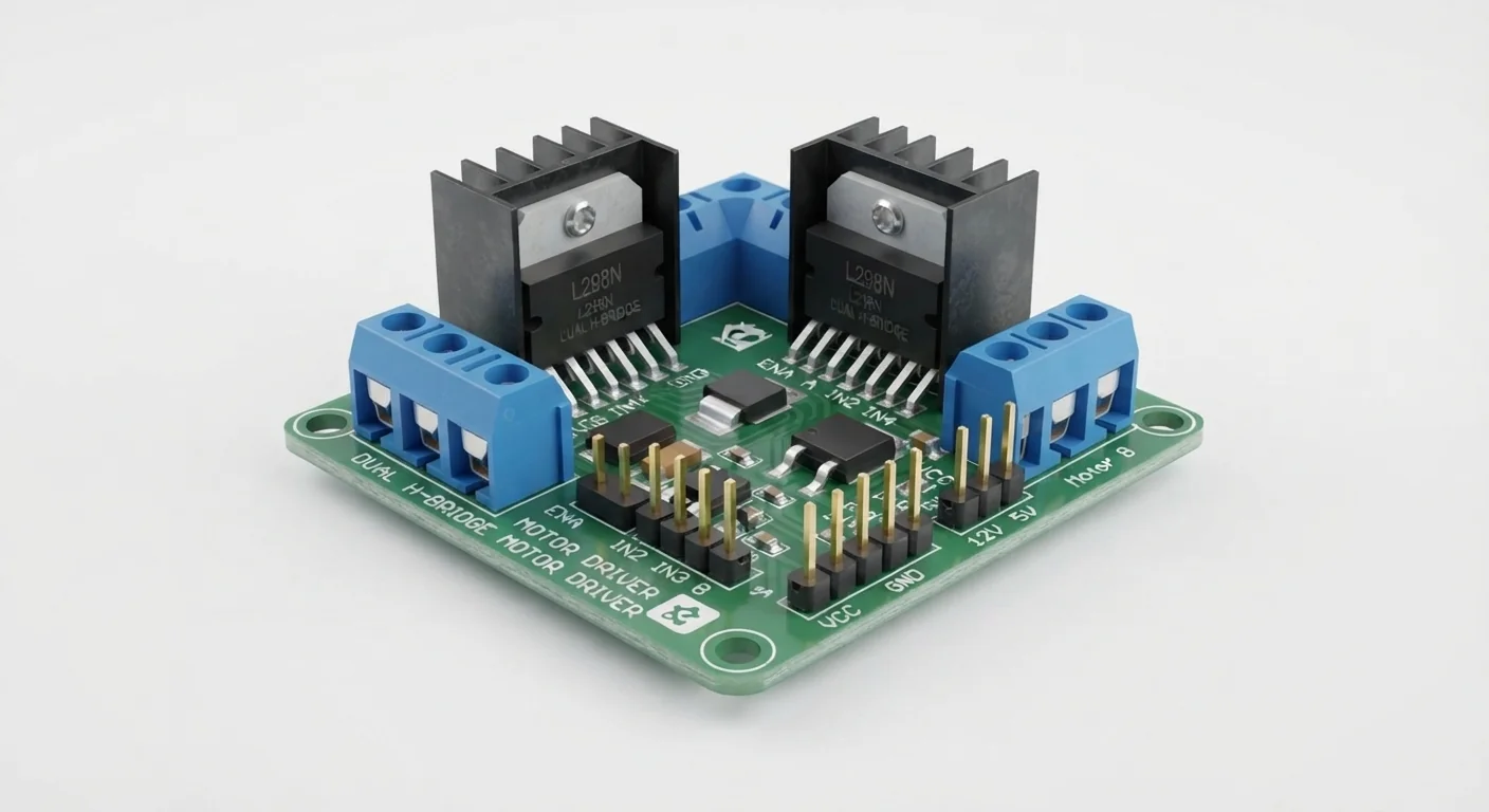
- A documented L298N breakout exposing ENA, IN1, IN2, OUT1/OUT2, motor supply, logic supply and ground. It must include correctly rated flyback diodes, decoupling, heatsinking and sense connections. The illustrated dual-chip board is not a verified breakout or pin map.
- Prerequisites and parts
- IDE setup; verified module schematic; documented low-current 6 V brushed motor; current-limited external 6 V motor supply and regulated 5 V logic supply; three 10 kiloohm pull-downs. Motor starting/stall current, voltage drop and thermal limits must fit the actual board. Secure the motor with no attached load.
- Expected result
- Motor turns one way for one second, coasts for two seconds, then turns the other way. ENA stays LOW at startup and between changes. Rotation direction depends on motor lead order; never stall it for testing.
- Verification limits
- Documentation and automated content/browser checks only in this update. No ESP32 compilation or physical hardware testing. The approved image depicts a component family; it does not authenticate a model, rating or terminal order.
Overview
An H-bridge reverses current through a motor. ENA disables bridge A independently of its two direction inputs. With ENA enabled, opposite input levels drive opposite directions; disabling ENA leaves the outputs inactive for a coast stop.
The L298 is a bipolar driver with appreciable voltage loss and heating. Its chip limits are not the continuous safe ratings of an unidentified board. For a small battery-powered robot, a suitable modern MOSFET driver may waste less power; verify that alternative separately.
Technical Specifications
Arduino library: Arduino-ESP32 3.x; no additional library
| Specification | Value | Why it matters |
|---|---|---|
| Logic supply | 5 V regulated in this example | Distinct from 3.3 V input logic; regulator arrangements are board-specific. |
| Motor rail | 6 V example, current-limited | Must match motor/board ratings and account for driver loss. |
| Startup | ENA LOW with external pull-down | Keeps motor disabled while ESP32 pins are high impedance. |
| Current capacity | Not inferred from illustration | Check stall/start current, diode, PCB, heatsink and thermal ratings. |
| Supply in this example | Example motor rail: external 6 V; logic rail: regulated 5 V through a board-documented external-input configuration. Never power the motor from ESP32 3.3 V or GPIO. | Applies only to the supported hardware assumptions above. |
| ESP32 signal compatibility | L298 chip IN/EN HIGH threshold is 2.3 V minimum; 3.3 V control is suitable only if the board has no conflicting 5 V pull-ups or interface. Common ground required. | Applies only to the supported hardware assumptions above. |
| Required protection | Disable the onboard regulator only by the exact board instructions before applying external logic power. Remove any documented ENA-to-5 V jumper before GPIO control. Add 10 kiloohm IN1/IN2/ENA pull-downs; qualify protection, supply current and temperature. | Applies only to the supported hardware assumptions above. |
Pinout
- ENA Remove only the documented ENA-high jumper; never join GPIO to a 5 V pull-up. GPIO25 with 10 kiloohm pull-down to GND Remove only the documented ENA-high jumper; never join GPIO to a 5 V pull-up.
- IN1 / IN2 3.3 V control after schematic verification. GPIO26 / GPIO27, each with 10 kiloohm pull-down 3.3 V control after schematic verification.
- OUT1 / OUT2 Swapping leads swaps direction; neither goes to ESP32 ground. Two motor leads Swapping leads swaps direction; neither goes to ESP32 ground.
- Motor supply / GND Current-limited supply; motor ratings and driver drop constrain operation. External 6 V / common GND Current-limited supply; motor ratings and driver drop constrain operation.
- Logic supply Only in the documented external-input mode; isolate onboard regulator output. Never connect to ESP32 3.3 V. External regulated 5 V Only in the documented external-input mode; isolate onboard regulator output. Never connect to ESP32 3.3 V.
- Unused bridge B Tie unused inputs to ground as board documentation permits; do not leave floating. ENB LOW; IN3/IN4 LOW; outputs unconnected Tie unused inputs to ground as board documentation permits; do not leave floating.
Wiring Diagram
Verified module: ENA/IN1/IN2 → GPIO25/26/27 with 10 kiloohm pull-downs; motor → OUT1/OUT2; separate 6 V motor and 5 V logic supplies; shared ground.
| Identified terminal | Connection | Qualification |
|---|---|---|
| ENA | GPIO25 with 10 kiloohm pull-down to GND | Remove only the documented ENA-high jumper; never join GPIO to a 5 V pull-up. |
| IN1 / IN2 | GPIO26 / GPIO27, each with 10 kiloohm pull-down | 3.3 V control after schematic verification. |
| OUT1 / OUT2 | Two motor leads | Swapping leads swaps direction; neither goes to ESP32 ground. |
| Motor supply / GND | External 6 V / common GND | Current-limited supply; motor ratings and driver drop constrain operation. |
| Logic supply | External regulated 5 V | Only in the documented external-input mode; isolate onboard regulator output. Never connect to ESP32 3.3 V. |
| Unused bridge B | ENB LOW; IN3/IN4 LOW; outputs unconnected | Tie unused inputs to ground as board documentation permits; do not leave floating. |
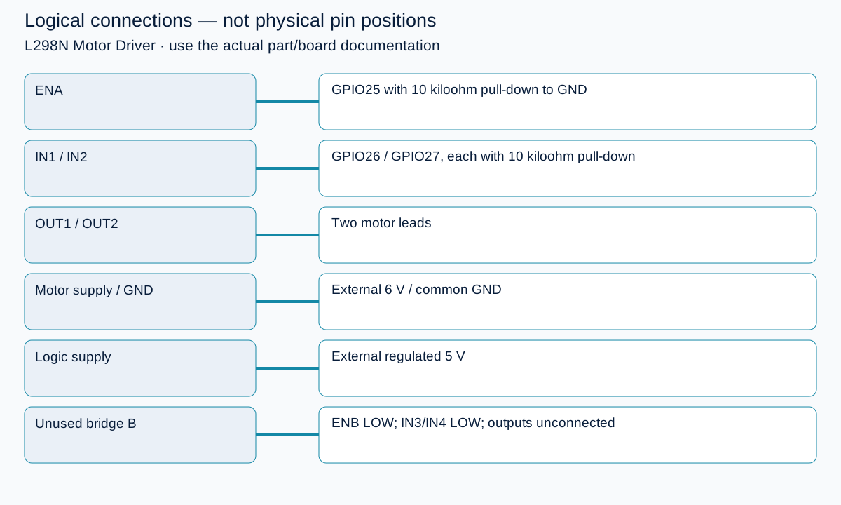
Open wiring diagram at full size (new tab)
-
1
With all power disconnected, find the real module schematic and regulator/jumper instructions. Stop if any terminal function or GPIO-facing voltage is unknown.
-
2
Confirm diodes, bypass capacitors, current/thermal limits and common ground; fit the three pull-downs and secure the unloaded motor.
-
3
Configure external logic power and ENA control only as documented; set the motor supply current limit below the verified circuit limit.
-
4
Power and upload with ENA held LOW; observe the standalone sequence. Disconnect power before touching wiring.
Wiring and matching Arduino code
One motor, disabled before reversal
Verified module: ENA/IN1/IN2 → GPIO25/26/27 with 10 kiloohm pull-downs; motor → OUT1/OUT2; separate 6 V motor and 5 V logic supplies; shared ground.
l298n_motor_driver_esp32.ino
#include <Arduino.h>
constexpr uint8_t ENA = 25, IN1 = 26, IN2 = 27;
void coast() {
  digitalWrite(ENA, LOW);
  digitalWrite(IN1, LOW);
  digitalWrite(IN2, LOW);
}
void runMotor(bool reverse) {
  coast();
  digitalWrite(IN1, reverse ? LOW : HIGH);
  digitalWrite(IN2, reverse ? HIGH : LOW);
  digitalWrite(ENA, HIGH);
}
void setup() {
  pinMode(ENA, OUTPUT);
  digitalWrite(ENA, LOW);
  pinMode(IN1, OUTPUT);
  pinMode(IN2, OUTPUT);
  coast();
  Serial.begin(115200);
  Serial.println("Disabled at startup; unloaded low-voltage motor only.");
  delay(2000);
}
void loop() {
  Serial.println("Direction A");
  runMotor(false);
  delay(1000);
  coast();
  Serial.println("Coast");
  delay(2000);
  Serial.println("Direction B");
  runMotor(true);
  delay(1000);
  coast();
  Serial.println("Coast");
  delay(2000);
}
Coast is not braking or guaranteed standstill. Increase the off interval for actual inertia; never reverse a still-spinning loaded motor with this demonstration. Software does not replace pull-downs or protection.
Expected Output
Motor turns one way for one second, coasts for two seconds, then turns the other way. ENA stays LOW at startup and between changes. Rotation direction depends on motor lead order; never stall it for testing.
How it works
Direction changes occur while ENA is LOW, after a coast interval. The example provides no closed-loop speed control, current sensing or fault handling. A stopped sketch cannot guarantee a safe motor; external enable bias, current limiting and an accessible power disconnect are required. Do not interpret a nominal chip current figure as a safe module operating current.
Troubleshooting
| Problem | Possible cause | Solution |
|---|---|---|
| Motor does not turn | ENA disabled, missing logic rail, supply current limit or driver voltage drop. | Check terminal voltages and configuration against the board schematic with motor power disconnected first. Do not raise supply above motor ratings to compensate blindly. |
| ESP32 resets when motor starts | Supply droop, motor noise or poor ground routing. | Keep motor current out of ESP32 supply paths; use documented decoupling and suitable separate rails. |
| Driver heats quickly | Excess load/current, short or inadequate heatsink. | Disconnect. Check motor stall current and board thermal ratings; reduce load or select a more appropriate driver. |
| Motor moves at startup | ENA pull-down missing or still tied to 5 V. | Power off; check the enable jumper/interface and external pull-down before another attempt. |
Where you use it
- Understanding enable versus direction
- Unloaded DC motor experiment
- Preparation for a documented robot driver interface
Continue learning
Related projects
FAQ
No. Its dual-chip layout is illustrative and not a documented module. Use the schematic and terminal labels of the actual purchased board.
Not assumed here. It may be a regulator output or logic input depending on board/jumpers. ESP32 stays on its own USB supply; only grounds are shared.
No. It tests bridge A only; bridge B is disabled. The linked robot has a different pin map and requires its own verified enable and power design.
Technical references
- Espressif GPIO API — Pin modes and digital output on Arduino-ESP32.
- ST L298 datasheet — Chip logic thresholds, supply separation, enable truth table, inductive protection and thermal limits; not an unknown module schematic.