
Before you start
- Board and software
- Low-voltage bench setup as specified below. ESP32 is optional for passive exercises. Coded examples require classic ESP32-WROOM-32/32E DevKit, unused exposed pins, Arduino IDE 2.x and Arduino-ESP32 3.3.2 (review baseline, not a latest-release claim). Other families need their own pin map.
- Supported hardware
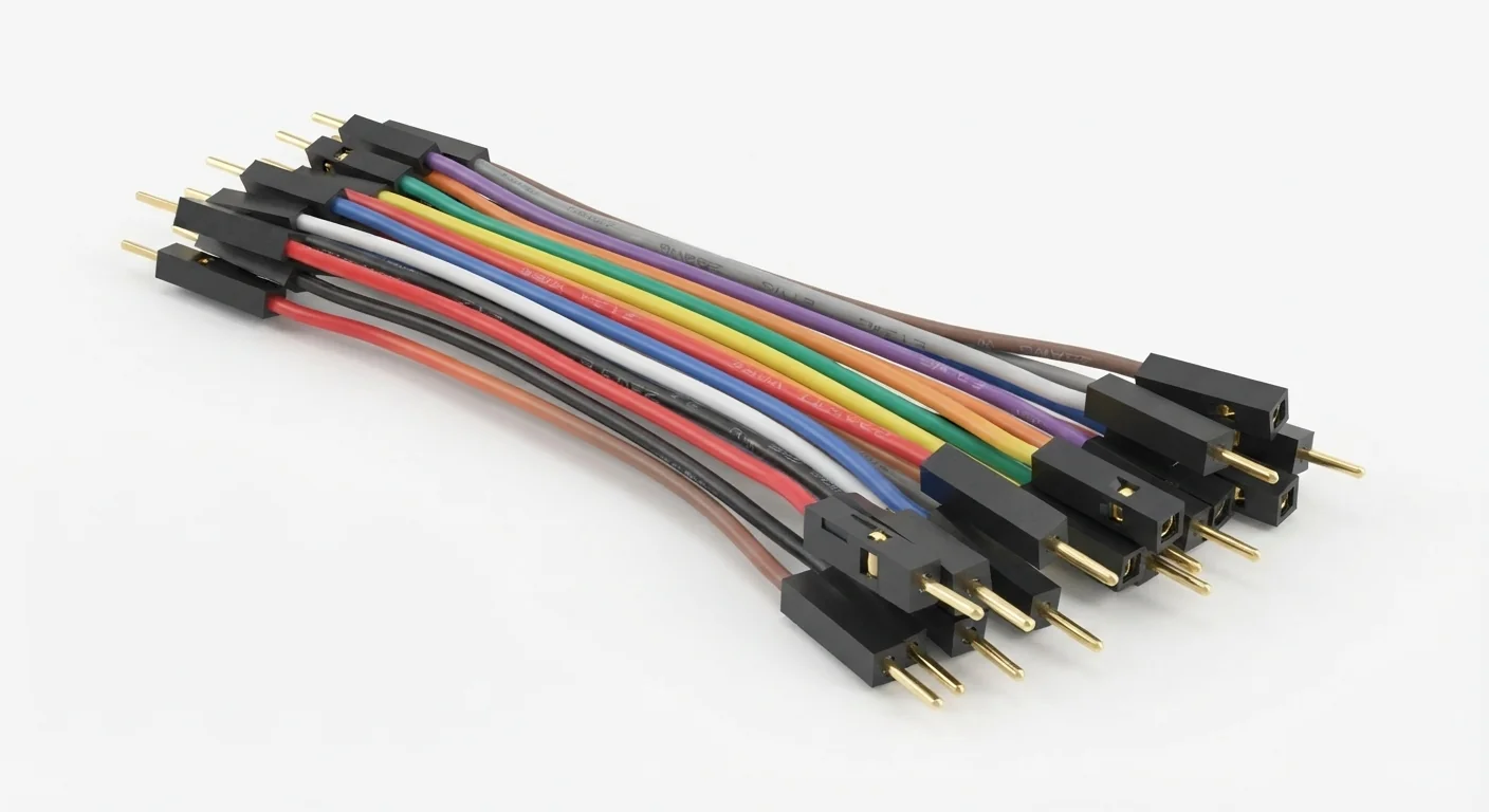
- Approved male-ended jumper-wire illustration. Entry 41 is another photo of this logical family, not another page. Gauge, conductor material and current rating are unspecified.
- Prerequisites and parts
- Unpowered wires, meter with continuity mode and actual mating headers. Use documented 2.54 mm headers where appropriate; verify fit without forcing.
- Libraries
- No firmware or library required for this exercise. Arduino-ESP32 3.3.2 is the site review baseline, not a dependency of this passive setup.
- Expected result
- Continuity exists end-to-end and not between separate wires; intended low-current connections match the wiring table.
- Verification status
- Documentation and source review only. Not compiled or tested on hardware. The approved product-style illustration identifies a family, not a verified physical pin layout or manufacturer-authenticated board. Follow the logical diagram and documentation for your actual part.
Overview
Male ends enter sockets; female ends fit pins. Choose male–male, male–female or female–female for the actual headers. Common prototyping headers use 2.54 mm spacing, but a connector shape does not prove pitch or contact quality.
Color is a useful convention, not electrical evidence. Keep a written pin map, use short leads for buses and pull on housings rather than wires. Check continuity with every supply removed; intermittent crimps can mimic software faults.
Technical Specifications
Arduino library: No firmware or library required for this exercise
| Specification | Value | Why it matters |
|---|---|---|
| Ends | Match actual pin/socket | Male/female describes contacts, not voltage. |
| Pitch | Often 2.54 mm | Verify actual mating header. |
| Current rating | Unspecified for artwork | Do not apply a universal motor-power rating. |
Pinout
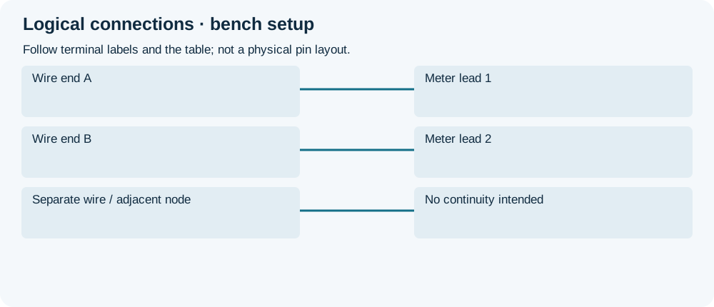
- Wire end A Connection Meter lead 1 All power removed.
- Wire end B Connection Meter lead 2 Check end-to-end continuity.
- Separate wire / adjacent node Connection No continuity intended Check for shorts before power.
Wiring Diagram
An isolated wire connects only its two ends; check intended joins and isolation before powering a circuit.
| Component terminal | ESP32 / circuit connection | Purpose and qualification |
|---|---|---|
| Wire end A | Meter lead 1 | All power removed. |
| Wire end B | Meter lead 2 | Check end-to-end continuity. |
| Separate wire / adjacent node | No continuity intended | Check for shorts before power. |
Open wiring diagram at full size (new tab)
-
1
Disconnect every power source.
-
2
Check end-to-end continuity and unwanted shorts.
-
3
Install by terminal labels, then review against the tutorial wiring table.
Expected Output
An isolated wire should give low end-to-end resistance within meter/lead limits. Flexing gently should not interrupt it. This does not certify current capacity or high-speed bus performance.
How it works
A wire joins two electrical nodes. Resistance, loose contacts and wire length affect real circuits. A ground wire provides a common reference but is not a substitute for properly routed high-current returns.
Troubleshooting
| Problem | Possible cause | Solution |
|---|---|---|
| Intermittent readings | Loose crimp or poor header fit. | Test unpowered while gently moving the wire; replace damaged leads. |
| Wrong pin despite correct color | Color used instead of labels. | Trace actual GPIO and module terminal labels end-to-end. |
| Warm connector | Excess current or poor contact. | Disconnect; use documented power wiring rather than more unknown jumpers. |
Where you use it
- Low-current breadboard connections
- Short SPI/I2C prototyping links with suitable pull-ups
FAQ
No. Label and verify the actual circuit.
No. It simply connects voltage from one node to another.
Technical references
- SparkFun connector basics — Header pitch and mating contacts; not ratings for the approved assortment.