
Before you start
- Board and software
- Classic ESP32-WROOM-32/32E DevKit with the listed GPIOs exposed and unused. Arduino IDE 2.x; esp32 by Espressif Systems 3.3.2 (review baseline, not a latest-release claim). Select the documented board or ESP32 Dev Module for a generic WROOM board. Other families need their own pin map. Serial Monitor: 115200 baud.
- Supported hardware
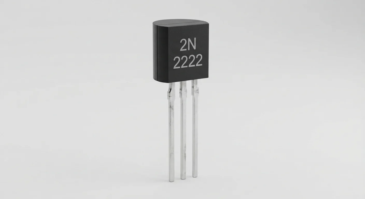
- Reference part: onsemi P2N2222A in TO-92, not every transistor sold as 2N2222 or PN2222. Its numbered leads are 1 collector, 2 base, 3 emitter. Read the manufacturer package view before wiring; the approved illustration does not establish manufacturer or pin order.
- Prerequisites and parts
- Complete IDE setup and Blink. Documented transistor, red indicator LED, 470 ohm LED resistor, 2.2 kOhm base resistor, 100 kOhm base-emitter pull-down and a breadboard. This example uses the DevKit 3.3 V rail for a few-mA LED load only.
- Libraries
- No extra library. Arduino-ESP32 3.3.2 GPIO and millis APIs.
- Expected result
- The external red LED switches ON for 500 ms and OFF for 1000 ms; Serial prints the commanded state, not a measured result.
- Verification status
- Documentation and source review only. Not compiled or tested on hardware. The approved product-style illustration identifies a family, not a verified physical pin layout or manufacturer-authenticated board. Follow the logical diagram and documentation for your actual part.
Overview
A small base current controls a larger collector current. In this low-side circuit the LED connects to the positive rail through its own resistor, while the emitter returns to ground. HIGH on GPIO25 supplies base current and turns the LED on.
Use this as a first switching circuit before an IR-emitter or buzzer project. A transistor is not a replacement for a motor driver or an LED current-limiting resistor. Similar part names can have opposite lead orders.
Technical Specifications
Arduino library: Arduino-ESP32 3.3.2 (no additional library)
| Specification | Value | Why it matters |
|---|---|---|
| Reference pin numbers | 1 collector / 2 base / 3 emitter | Match onsemi package orientation; not a universal 2N2222 arrangement. |
| Load | One red LED, 470 ohm series resistor | (3.3 V - LED drop - transistor drop) / 470 ohm is the design estimate. |
| Base resistor | 2.2 kOhm | Roughly 1 mA at a 0.7 V base-emitter drop; not a measured value. |
Pinout
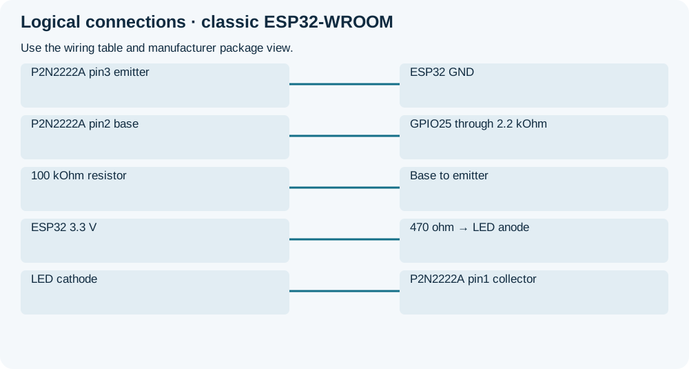
- P2N2222A pin3 emitter Return ESP32 GND Verify numbered package view.
- P2N2222A pin2 base Control GPIO25 through 2.2 kOhm Series base resistor required.
- 100 kOhm resistor Pull-down Base to emitter Keeps transistor off with input floating.
- ESP32 3.3 V Load supply 470 ohm → LED anode Anode to resistor; no bare LED across supply.
- LED cathode Load return P2N2222A pin1 collector Collector switches LED current to emitter.
Wiring Diagram
GPIO25 → 2.2 kOhm → base; emitter/GND common; 100 kOhm base-emitter. 3.3 V → 470 ohm → red LED anode; cathode → collector.
| Component terminal | ESP32 / circuit connection | Purpose and qualification |
|---|---|---|
| P2N2222A pin3 emitter | ESP32 GND | Verify numbered package view. |
| P2N2222A pin2 base | GPIO25 through 2.2 kOhm | Series base resistor required. |
| 100 kOhm resistor | Base to emitter | Keeps transistor off with input floating. |
| ESP32 3.3 V | 470 ohm → LED anode | Anode to resistor; no bare LED across supply. |
| LED cathode | P2N2222A pin1 collector | Collector switches LED current to emitter. |
Open wiring diagram at full size (new tab)
-
1
Unplug USB. Identify the onsemi part and its numbered leads from the package drawing.
-
2
Wire the LED and both base resistors; inspect for rail shorts.
-
3
Upload, then open Serial Monitor at 115200; compare LED behavior with the commands.
Wiring and matching Arduino code
Small LED low-side switch
GPIO25 → 2.2 kOhm → base; emitter/GND common; 100 kOhm base-emitter. 3.3 V → 470 ohm → red LED anode; cathode → collector.
2n2222_npn_transistor.ino
#include <Arduino.h>
constexpr uint8_t OUTPUT_PIN = 25;
bool active = false;
uint32_t changedAt = 0;
void setup() {
  Serial.begin(115200);
  pinMode(OUTPUT_PIN, OUTPUT);
  digitalWrite(OUTPUT_PIN, LOW);
  Serial.println("Starts OFF; repeating on/off demonstration");
}
void loop() {
  const uint32_t now = millis();
  const uint32_t interval = active ? 500 : 1000;
  if (now - changedAt >= interval) {
    changedAt = now;
    active = !active;
    digitalWrite(OUTPUT_PIN, active ? HIGH : LOW);
    Serial.println(active ? "ON" : "OFF");
  }
}
The sketch commands GPIO25, not an onboard LED. The pull-down provides hardware bias before setup. HIGH is ON in this exact NPN circuit.
Expected Output
After one second OFF, the LED should blink with a half-second ON interval. Printed ON/OFF confirms software intent; it does not detect LED current, polarity or a wiring fault.
How it works
The base-emitter junction needs limited current. The LED resistor determines load current; transistor gain alone does not set it. Calculate base drive for a new load using saturation conditions, GPIO limits and the exact datasheet. The datasheet’s 600 mA absolute maximum is not permission to switch that current from this circuit. Inductive loads require appropriate suppression and a fresh electrical design.
Troubleshooting
| Problem | Possible cause | Solution |
|---|---|---|
| LED never lights | Reversed LED, wrong C/E order or missing common ground. | Power off; check the manufacturer pin view, LED polarity and series resistors. |
| LED stays on | Collector/emitter short or base held high. | Check breadboard rows and base pull-down; compare GPIO state with Serial. |
| Part heats up | Short, excessive load or incorrect base drive. | Disconnect power. Return to the small LED load; do not transplant this design into a motor circuit. |
Where you use it
- Small low-voltage indicators
- Learning low-side switching
- Preparation for a documented IR LED driver
Continue learning
Related projects
FAQ
Only after checking that exact manufacturer’s pinout and electrical data. The numbered reference here is onsemi P2N2222A.
Not automatically. A larger load needs different base drive; the linked buzzer example uses its own resistor calculation.
Technical references
- onsemi P2N2222A datasheet — Reference lead numbering, saturation test conditions and ratings.
- Arduino-ESP32 3.3.2 — Pinned GPIO and timing baseline; not compiled.
- Arduino-ESP32 3.3.2 GPIO implementation — Initialize the GPIO bus with pinMode before digitalWrite; hardware pull-down provides reset bias.