
Before you start
- Board and software
- Classic ESP32-WROOM-32/32E DevKit with the listed GPIOs exposed and unused. Arduino IDE 2.x; esp32 by Espressif Systems 3.3.2 (review baseline, not a latest-release claim). Select the documented board or ESP32 Dev Module for a generic WROOM board. Other families need their own pin map. Serial Monitor: 115200 baud.
- Supported hardware
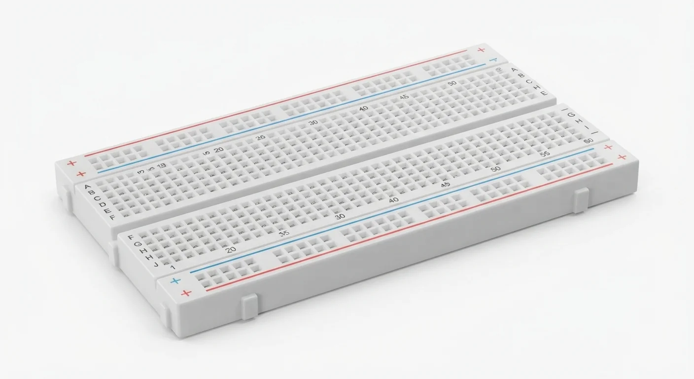
- Conventional solderless breadboard with documented arrangement, checked by continuity before power. No exact tie-point count, rail continuity or current rating inferred from the illustration.
- Prerequisites and parts
- Complete IDE setup. Known red indicator LED suitable for a few mA, 470 ohm 0.25 W resistor, jumpers and continuity meter. GPIO25 exposed/unused. No assumed onboard LED.
- Libraries
- Arduino-ESP32 3.3.2 GPIO only; no breadboard library.
- Expected result
- External red LED blinks one second on/off with its terminals in separate nodes.
- Verification status
- Documentation and source review only. Not compiled or tested on hardware. The approved product-style illustration identifies a family, not a verified physical pin layout or manufacturer-authenticated board. Follow the logical diagram and documentation for your actual part.
Overview
A solderless breadboard holds leads in spring contacts so a circuit can be rearranged. Holes on one internal strip are one electrical node; spacing alone does not tell you where connections go.
Conventional boards connect each five-hole terminal group, with the center trench separating sides. Power rails may split midway and opposite-side rails are usually independent. Letters, numbers and red/blue lines are labels, not a continuity test. Map the actual board with all power removed. A wide DevKit may cover usable holes; use jumper leads or two boards rather than force a fit.
Technical Specifications
Arduino library: Arduino-ESP32 3.3.2 built-in GPIO; no breadboard library.
| Specification | Value | Why it matters |
|---|---|---|
| Connection pattern | Verify strips and rails | Five-hole groups/split rails are typical, not universal. |
| LED circuit | GPIO25 → 470 ohm → anode; cathode → GND | Each component end needs a different node except intended junctions. |
| Estimated current | About 2.8 mA assuming 2.0 V LED | (3.3−2.0)/470; actual brightness/voltage varies. |
| Pin label | GPIO25, not a hole number | Breadboard row numbers are placement labels only. |
Pinout
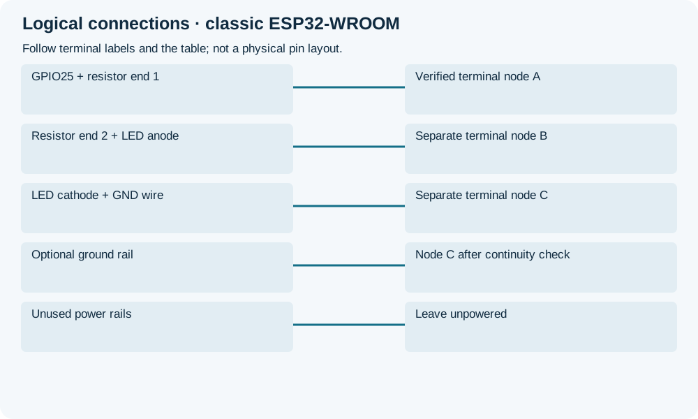
- GPIO25 + resistor end 1 Output Verified terminal node A A is a logical node name, not column A.
- Resistor end 2 + LED anode Junction Separate terminal node B Must not share metal strip with A.
- LED cathode + GND wire Return Separate terminal node C C connects to DevKit GND.
- Optional ground rail Distribution Node C after continuity check Bridge splits only when needed.
- Unused power rails Unused Leave unpowered No supply module required.
Wiring Diagram
GPIO25 → A → 470 ohm → B → LED anode; cathode → C → GND. A/B/C are separate verified electrical nodes.
| Component terminal | ESP32 / circuit connection | Purpose and qualification |
|---|---|---|
| GPIO25 + resistor end 1 | Verified terminal node A | A is a logical node name, not column A. |
| Resistor end 2 + LED anode | Separate terminal node B | Must not share metal strip with A. |
| LED cathode + GND wire | Separate terminal node C | C connects to DevKit GND. |
| Optional ground rail | Node C after continuity check | Bridge splits only when needed. |
| Unused power rails | Leave unpowered | No supply module required. |
Open wiring diagram at full size (new tab)
-
1
Unplug all supplies. Check terminal-group, cross-trench and rail continuity; record which holes share a node.
-
2
Place resistor across A/B, LED across B/C, GPIO25 wire to A and GND to C. Confirm LED polarity from actual markings/datasheet, not trimmed lead length.
-
3
Check no GPIO-to-GND short and no component has both leads in one strip. Upload complete sketch and observe external LED.
Wiring and matching Arduino code
External LED on separate nodes
GPIO25 → A → 470 ohm → B → LED anode; cathode → C → GND. A/B/C are separate verified electrical nodes.
solderless_breadboard.ino
#include <Arduino.h>
constexpr uint8_t LED_PIN = 25;
void setup() {
  pinMode(LED_PIN, OUTPUT);
  digitalWrite(LED_PIN, LOW);
}
void loop() {
  digitalWrite(LED_PIN, HIGH);
  delay(1000);
  digitalWrite(LED_PIN, LOW);
  delay(1000);
}
Complete external LED example; pinMode before digitalWrite. Delay is suitable for this single-task first exercise, not a multitask application. Row labels do not change code.
Expected Output
LED should alternate on/off each second. Darkness, constant light or resets need inspection, not congratulations. The 2.8 mA value is calculated using an assumed red-LED voltage, not measured.
How it works
Resistor and LED share only their intended junction B, so current passes through the resistor. Both resistor ends in one strip bypass it; both LED leads in one strip short the LED. Routing is a translation of electrical nodes, not an illustration to copy without connectivity checks.
Troubleshooting
| Problem | Possible cause | Solution |
|---|---|---|
| No light | Reversed LED, wrong GPIO, bad contact or same-node leads. | Unplug and trace A/B/C and polarity. |
| Reset or warming | Power/GPIO short or unsafe supply module. | Disconnect and inspect unpowered; do not use a bigger source. |
| Half a rail is dead | Rail center split. | Check unpowered continuity; bridge only intended matching nodes. |
| Works only when pressed | Bad contact or jumper. | Replace suspect parts and secure leads; one brief result does not prove stability. |
Where you use it
- Low-current Blink/button lessons
- Sensor prototypes with verified rails
- Mapping wiring tables to electrical nodes
Continue learning
FAQ
No. They label passive contacts; supply and continuity must be checked.
Not on an unspecified board. Use actual connector/current ratings and suitable direct power paths.
Technical references
- SparkFun breadboard anatomy — Manufacturer teaching material on strips, trench and split rails.
- SparkFun reference board — A documented board with split buses, not identification of the artwork.
- Arduino-ESP32 3.3.2 GPIO — Pinned GPIO implementation.