
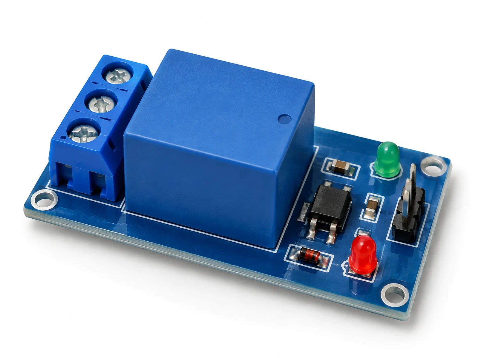
Plain-English Overview
A relay module is a remote-controlled switch. Your ESP32 sends a small signal to the relay input, and the relay clicks to open or close a separate circuit.
That separate circuit can control a larger load than an ESP32 pin can handle, such as a small pump, fan, lamp, or solenoid. The ESP32 does not power the load directly; it only tells the relay when to switch.
Start with low-voltage DC loads. Mains AC wiring can injure or kill people and should only be handled by qualified adults using proper enclosures, fuses, strain relief, and local electrical rules.
Where You Use It
- Low-voltage pump control
- Fan switching
- Lamp automation demo
- Irrigation valve control
- Alarm siren control
- Classroom switch experiment
- Power strip prototype
- Heater control with safety supervision
Quick Facts
- Function Electrically controlled switch
- Input behavior Often active LOW
- Contacts COM, NO, NC
- Isolation Often optocoupler/transistor driven
- Best first load Low-voltage DC fan or LED strip
- GPIO safety Use module input, not bare coil
How It Works
A relay contains an electromagnet and a mechanical switch. When the module energizes the coil, the switch moves with a click. COM connects either to NC or NO depending on whether the relay is off or on.
NO means normally open: the load is off until the relay activates. NC means normally closed: the load is on until the relay activates. COM is the moving common terminal.
The ESP32 GPIO does not power the relay coil directly. A relay module usually includes a transistor driver, diode, indicator LED, and sometimes optocoupler isolation. The GPIO only controls the input side.
Many modules are active LOW because of the input circuit design. That means digitalWrite(RELAY_PIN, LOW) turns the relay on and HIGH turns it off. Production code should define RELAY_ON and RELAY_OFF constants so the logic is obvious.
Technical Specifications
Arduino library: Built-in Arduino digitalWrite
| Specification | Value | Why it matters |
|---|---|---|
| Module supply | Often 5 V | Most relay coils need more current than the ESP32 3.3 V rail should provide. |
| Input signal | 3.3 V may work on many modules; verify yours | Some 5 V relay modules do not trigger reliably from 3.3 V logic. |
| Contact rating | Often printed as 10 A 250 VAC or 10 A 30 VDC | The printed maximum is not a beginner design target. |
| Isolation | Module dependent | Optocoupler labels do not guarantee safe mains layout. |
| Switch type | SPDT: COM, NO, NC | One moving contact can connect to either of two terminals. |
| Response | Mechanical milliseconds | Fine for pumps/lights, not for fast PWM. |
| Coil current | Often 60-90 mA | Too much for direct GPIO drive. |
| Load type | Resistive loads easiest; inductive loads need protection | Motors and solenoids create voltage spikes. |
| Default state | Off when input inactive if wired to NO | Important for fail-safe design. |
| Safety | Use enclosure and fuse for hazardous voltage | Relay contacts can expose dangerous voltage. |
Pinout
- VCC Module power 5 V supply Powers relay coil and input circuit on common modules.
- GND Ground reference ESP32 GND Needed unless using true isolated wiring per module documentation.
- IN Control input ESP32 GPIO26 Often active LOW; test before connecting real loads.
- COM Common switch terminal Load power input Moving contact of the relay switch.
- NO Normally open terminal Load switched output Use when load should be off by default.
- NC Normally closed terminal Optional always-on path Use only when you understand fail-safe behavior.
Wiring Diagram
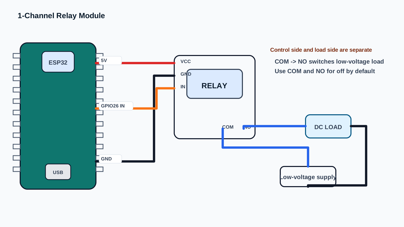
The control side connects to the ESP32. The contact side connects in series with the load power circuit. These two sides are different jobs.
For a beginner test, switch a low-voltage LED strip, buzzer, or small fan. Do not put mains voltage on a breadboard.
-
1
Unplug all power before wiring.
-
2
Connect relay VCC to a suitable 5 V supply.
-
3
Connect relay GND to ESP32 GND.
-
4
Connect relay IN to ESP32 GPIO26.
-
5
For a low-voltage load, connect supply positive to COM.
-
6
Connect NO to the load positive wire.
-
7
Connect the load negative wire back to the load supply negative.
-
8
Upload test code before connecting valuable equipment.
Code Examples
Use the same wiring with Arduino IDE, PlatformIO, or ESP-IDF. Start with Arduino, then graduate when you need a larger project structure.
#define RELAY_PIN 26

const int RELAY_ON = LOW;
const int RELAY_OFF = HIGH;

void setup() {
  Serial.begin(115200);
  pinMode(RELAY_PIN, OUTPUT);
  digitalWrite(RELAY_PIN, RELAY_OFF);
  Serial.println("Relay module test. Load should start OFF.");
}

void loop() {
  Serial.println("Relay ON");
  digitalWrite(RELAY_PIN, RELAY_ON);
  delay(2000);

  Serial.println("Relay OFF");
  digitalWrite(RELAY_PIN, RELAY_OFF);
  delay(2000);
}#include <Arduino.h>
#define RELAY_PIN 26
const int RELAY_ON = LOW;
const int RELAY_OFF = HIGH;
void setup() {
Serial.begin(115200);
pinMode(RELAY_PIN, OUTPUT);
digitalWrite(RELAY_PIN, RELAY_OFF);
Serial.println("Relay module test. Load should start OFF.");
}
void loop() {
Serial.println("Relay ON");
digitalWrite(RELAY_PIN, RELAY_ON);
delay(2000);
Serial.println("Relay OFF");
digitalWrite(RELAY_PIN, RELAY_OFF);
delay(2000);
}// ESP-IDF starter structure for this component.
// Keep the wiring from the pinout section, then move the read/write logic into app_main().
#include <stdio.h>
#include "freertos/FreeRTOS.h"
#include "freertos/task.h"
void app_main(void) {
printf("1-Channel Relay Module ready\n");
while (true) {
// Add component read/write code here.
vTaskDelay(pdMS_TO_TICKS(1000));
}
}The constants RELAY_ON and RELAY_OFF make active-LOW behavior explicit. setup() starts with the relay off before configuring normal operation.
loop() toggles the relay slowly so you can hear the click and measure the contact state. Do not use relay modules for rapid PWM; mechanical contacts wear out.
Expected Output
The relay clicks on for two seconds, then clicks off for two seconds. Serial Monitor prints Relay ON and Relay OFF. If the LED on the relay module changes but your load does not, the contact-side wiring is wrong or the load supply is missing.
Common Mistakes
- Switching mains voltage on a breadboard.
- Assuming HIGH always means relay on.
- Connecting a motor directly to ESP32 instead of through contacts/driver.
- Forgetting common ground on the control side.
- Using the NC terminal when NO was intended.
- Powering a 5 V relay coil from the ESP32 3V3 pin.
- Rapidly toggling a mechanical relay.
- Ignoring flyback protection for inductive DC loads.
- Confusing module input pins with contact terminals.
- Testing with dangerous loads before proving code on low voltage.
Troubleshooting
| Problem | Possible cause | Solution |
|---|---|---|
| Relay does not click | No 5 V coil power, wrong GPIO, or input logic mismatch. | Check VCC/GND, try active LOW, and measure IN voltage. |
| Relay clicks but load stays off | COM/NO/NC wiring or load supply is wrong. | Wire load supply through COM and NO for off-by-default behavior. |
| Relay is on at boot | Active LOW input floats or boot state triggers module. | Use pull-up, safe boot pin, or external driver logic. |
| ESP32 resets when relay switches | Power dip or coil/load noise. | Use separate relay supply, common ground, and proper suppression. |
| Module LED turns on but no click | Insufficient coil voltage/current. | Use rated 5 V supply for the relay module. |
| GPIO gets hot or damaged | Bare relay coil connected directly. | Use a relay module or transistor driver with flyback diode. |
| Load turns on opposite of code | NC used instead of NO or active LOW logic. | Move wire to NO or invert constants. |
| Motor causes false resets | Inductive noise from load. | Add flyback diode/snubber and separate power wiring. |
| Relay chatters | Weak supply or noisy input. | Use stable supply and avoid floating control pin. |
| No isolation despite optocoupler | JD-VCC jumper/wiring not configured for isolation. | Follow your module schematic; do not assume isolation. |
| Mains wiring unsafe | Exposed contacts or no enclosure. | Stop and use proper rated enclosure, fuse, and qualified supervision. |
| Relay too slow for dimming | Mechanical contacts are not PWM devices. | Use MOSFET or solid-state driver for fast switching. |
| Contacts wear out | Switching high current or frequent cycles. | Use rated relay and reduce switching frequency. |
| ESP32 cannot trigger 5 V module | Input threshold too high. | Use transistor driver or 3.3 V compatible relay module. |
| Load always on | Wired through NC. | Use NO for normally-off projects. |
Related Guides
Related Projects
FAQ
It is an electrically controlled switch module.
No. Use a driver transistor or relay module.
Many modules use input circuits that energize when IN is pulled LOW.
COM is the moving contact, NO is open when off, and NC is closed when off.
Use COM and NO so the load is off by default.
Only with qualified supervision, proper enclosure, fuse, strain relief, and local electrical compliance.
Yes. Low-voltage DC loads are best for learning.
Often yes, especially if the coil current causes ESP32 resets.
No. Use MOSFET or solid-state switching for PWM.
The internal mechanical switch moves when the coil energizes.
Yes if rated properly, but motors need flyback/noise protection.
No. Board layout and jumper wiring determine real isolation.
GPIO26 is a good beginner output pin.
Boot pin states or floating inputs can briefly trigger modules.
Yes if designed for 3.3 V coil/input.
Contacts can switch rated AC or DC, but ratings differ.
The contact-side circuit may not have a complete power path.
For normal module control, yes. True isolation wiring is module-specific.
Some modules use JD-VCC for separate relay coil power.
A MOSFET module is often quieter, faster, and longer-lasting.
COM is the moving relay contact that connects to NO when the relay is energized or NC when it is off.
Active LOW means the module turns on when the ESP32 drives the input LOW instead of HIGH.
Use a low-voltage DC LED strip segment, buzzer, or small lamp with current below the module rating.
Stop before any mains wiring unless a qualified adult handles enclosure, fuse, strain relief, and local electrical rules.
Have them prove IN logic, relay click, COM/NO continuity, and low-voltage load wiring with power disconnected first.
It separates safe GPIO control from a separate load circuit and shows why ratings, isolation, and default-off wiring matter.
Use Serial Monitor and an LED load to compare HIGH and LOW commands before connecting any larger device.
Use a multimeter continuity test with the load power disconnected to observe which contact is closed in each relay state.
Mechanical relays are slow and wear out; use a MOSFET or driver for fast dimming or speed control.
COM and NO keep the beginner load off by default until code deliberately energizes the relay.
1-Channel Relay Module is a power and switching part used with the ESP32. Learn its job first, then connect power, ground, and signal pins exactly as the wiring table shows.
A signal pin is the wire that carries information between the ESP32 and the component. It may be digital, analog, I2C, SPI, PWM, or another protocol depending on the part.
For a beginner ESP32 lesson, this component is suitable when an adult checks the wiring, keeps the project at low voltage, and unplugs USB before moving jumper wires.
Watch for reversed power pins, loose jumper wires, and children touching the circuit while it is powered. Most beginner ESP32 mistakes are wiring mistakes, not broken parts.
Use 1-Channel Relay Module to connect one visible hardware behavior to one software concept. Ask students to predict the reading or output first, then test it on real hardware.
Assess whether students can explain the wiring, identify the ESP32 pins used, run the example, describe the expected output, and troubleshoot one intentional mistake.
Change one variable at a time: move to another valid GPIO, adjust the timing, display the value on an OLED, or combine the component with a related project.
Disconnect one wire, predict the failure, observe the output, then explain why the failure happened before reconnecting the circuit.
Unplug USB power first. Then check the pin labels, voltage level, and ground connection before powering the ESP32 again.
Common ground gives the ESP32 and the component the same voltage reference. Without it, signal readings can be wrong or unstable.
Review, Testing, and References
Author: Abdul Mubeen and the ESP32 Engine editorial team. Last updated: 2026-07-05. Reviewed: wiring, code, beginner safety, and ESP32 compatibility. Educational level: Beginner.
Use this component page as an educational starting point. Check official documentation before using the part in production, high-current, outdoor, battery, or safety-critical hardware.
Downloads
Relay modules vary by board. Check the exact module markings, schematic, coil voltage, input trigger type, and contact rating before connecting real loads.
No separate datasheet is needed for this beginner guide.