
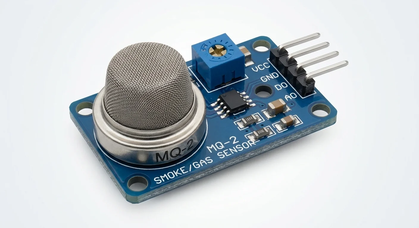
Before you start
- Board and software
- Classic ESP32-WROOM-32/32E DevKit with the listed GPIOs exposed and unused. Arduino IDE 2.x; esp32 by Espressif Systems 3.3.2 (review baseline, not a latest-release claim). Select the documented board or ESP32 Dev Module for a generic WROOM board. Other families need their own pin map. Serial Monitor: 115200 baud.
- Supported hardware
- Documented MQ-2 analog breakout with VCC, GND and AO, a 5.0 V heater/circuit supply and a nonnegative AO bounded by that supply. Verify the purchased schematic, labels and load resistor. Not a bare six-pin sensor circuit; no exact carrier revision or authenticity established by the illustration.
- Prerequisites and parts
- Complete IDE setup and analog-input lesson. Regulated external 5.0 V ±0.1 V supply sized for the heater plus actual carrier load, two 10 kohm 1% resistors, 100 nF ceramic capacitor, meter and short wires. DevKit stays on USB; do not join its positive power rail to the sensor supply. Heater alone can require about 190 mA at 5 V from the 950 mW limit; account for carrier overhead. GPIO32 must be free.
- Libraries
- Arduino-ESP32 3.3.2 built-in ADC; no gas-concentration library.
- Expected result
- Once powered, Serial reports raw ADC counts and calibrated estimates of divider-node millivolts once per second. There is no ppm, AQI or alarm result.
- Verification status
- Documentation and source review only. Not compiled or tested on hardware. The approved product-style illustration identifies a family, not a verified physical pin layout or manufacturer-authenticated board. Follow the logical diagram and documentation for your actual part.
Overview
MQ-2 is a heated metal-oxide sensor sensitive to propane, smoke and other combustible gases. A breakout turns its resistance change into an analog voltage; its comparator output, if fitted, is a separate threshold signal. This exercise reads AO only.
Treat it as a voltage-reading lesson. Do not release fuel, solvents or smoke to test it, and do not replace a certified alarm with this circuit. Changing temperature, humidity, oxygen and sensor history can change the baseline. A trimmer is not gas calibration.
Technical Specifications
Arduino library: Arduino-ESP32 3.3.2 built-in ADC; no additional library.
| Specification | Value | Why it matters |
|---|---|---|
| Heater/circuit reference | 5.0 V ±0.1 V | Winsen conditions for the stated sensor; check the carrier schematic. |
| AO interface | Two 10 kohm 1% resistors + 100 nF | Divider reduces voltage; it also loads AO by 20 kohm. |
| ADC input | GPIO32, ADC1, ADC_11db | 12-bit raw counts; calibrated millivolts are a separate conversion. |
| Initial conditioning | MQ-2: at least 48 hours | Manufacturer test preheat, not a sketch delay or guaranteed stabilization time. |
Pinout
- Sensor VCC Supply External regulated 5.0 V Only the documented 5 V carrier; not ESP32 3.3 V.
- Sensor GND / supply minus Reference ESP32 GND Common reference; positive supplies stay separate.
- Sensor AO Analog output 10 kohm R1 then node N Never connect AO directly to GPIO.
- Node N Divider GPIO32; 10 kohm R2 to GND Both resistors 1%; verify voltage before attachment.
- 100 nF ceramic capacitor Filter Node N to GND Place close to ADC input; no polarity.
- Sensor DO, if fitted Comparator Leave disconnected Threshold/polarity and pull-up rail are carrier-specific.
Wiring Diagram
External 5 V → sensor VCC; all grounds common. AO → R1 10 kohm → N → GPIO32. R2 10 kohm and 100 nF both connect N to GND. DO unused.
| Component terminal | ESP32 / circuit connection | Purpose and qualification |
|---|---|---|
| Sensor VCC | External regulated 5.0 V | Only the documented 5 V carrier; not ESP32 3.3 V. |
| Sensor GND / supply minus | ESP32 GND | Common reference; positive supplies stay separate. |
| Sensor AO | 10 kohm R1 then node N | Never connect AO directly to GPIO. |
| Node N | GPIO32; 10 kohm R2 to GND | Both resistors 1%; verify voltage before attachment. |
| 100 nF ceramic capacitor | Node N to GND | Place close to ADC input; no polarity. |
| Sensor DO, if fitted | Leave disconnected | Threshold/polarity and pull-up rail are carrier-specific. |
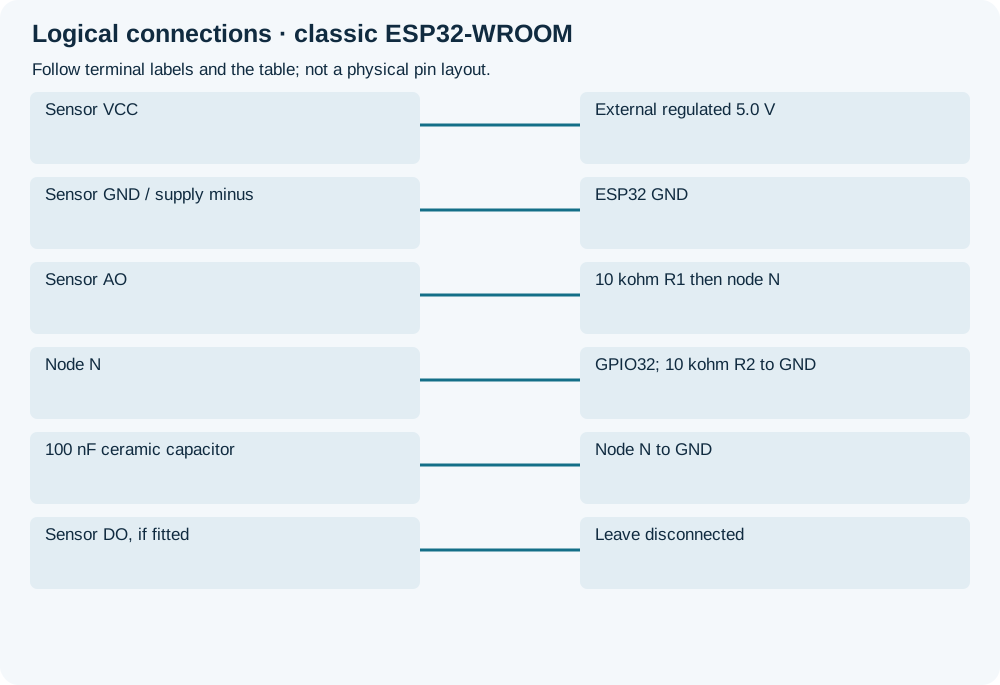
Open wiring diagram at full size (new tab)
-
1
Unplug both supplies; identify AO/VCC/GND from the actual schematic. Verify the divider and capacitor node; do not copy physical pin positions from the artwork.
-
2
With ESP32 signal disconnected, power the sensor, check supply and node voltages. Disconnect power again before attaching GPIO32.
-
3
Upload, power both systems and open 115200 baud. Follow manufacturer conditioning for any repeatable study; startup readings are not readiness evidence. Do not introduce hazardous test gases.
Wiring and matching Arduino code
MQ-2 divided-voltage logger
External 5 V → sensor VCC; all grounds common. AO → R1 10 kohm → N → GPIO32. R2 10 kohm and 100 nF both connect N to GND. DO unused.
mq2_gas_smoke_sensor.ino
#include <Arduino.h>
constexpr uint8_t SENSOR_ADC = 32;
uint32_t lastReport = 0;
void setup() {
  Serial.begin(115200);
  analogReadResolution(12);
  analogSetPinAttenuation(SENSOR_ADC, ADC_11db);
  Serial.println("AO through 10k/10k divider; readings are not ppm.");
}
void loop() {
  const uint32_t now = millis();
  if (now - lastReport >= 1000) {
    lastReport = now;
    const uint16_t raw = analogRead(SENSOR_ADC);
    const uint32_t nodeMv = analogReadMilliVolts(SENSOR_ADC);
    Serial.printf("raw=%u node_mV=%lu\n",
                  static_cast<unsigned>(raw),
                  static_cast<unsigned long>(nodeMv));
  }
  delay(1);
}
Raw counts and calibrated millivolts are two successive samples, not one identical sample converted twice. No voltage-to-ppm formula, automatic alarm threshold or sensor-ready indication. GPIO32 avoids classic ESP32 ADC2/Wi-Fi contention.
Expected Output
Lines such as raw=<count> node_mV=<estimate> should appear once a second; these are format placeholders, not measured values. Compare node_mV with a meter. The signal may drift during heating. The sketch does not declare the sensor conditioned or identify a gas.
How it works
The equal-resistor divider halves the connected AO voltage in the ideal circuit. Its 20 kohm load can change an unbuffered carrier’s effective load resistance and therefore its transfer curve; do not reuse the bare-sensor calibration curve unchanged. The capacitor helps slow noise at the ADC node. Calibrated ADC millivolts are still an estimate, not a calibration of the gas sensor.
Follow the actual sensor’s storage/reconditioning and manufacturer test conditions for later studies. Initial 48-hour-class conditioning is not a promise that every power-up requires exactly that delay or that subsequent readings are accurate. There is no defensible universal clean-air count.
Troubleshooting
| Problem | Possible cause | Solution |
|---|---|---|
| ADC stays near full scale | Missing divider, wrong node or excessive voltage. | Disconnect GPIO first and measure N; verify R1/R2 and supply. Attenuation does not protect an overvoltage input. |
| Baseline keeps moving | Heater conditioning, environment or supply changes. | Check actual conditioning procedure and stable power; log context rather than converting drift to ppm. |
| ESP32 resets | Heater shares an inadequate supply path or ground wiring. | Use the qualified external source, check its current budget and keep positive rails separate. |
| DO LED disagrees with AO | Comparator threshold or output circuit differs. | DO is not read here. Check the actual schematic; its LED is not a calibrated alarm. |
| Reading seems too low | Divider loading or ADC response. | Measure both AO and N; characterize the connected circuit before any conversion. Do not assume AO is unchanged by added resistors. |
Where you use it
- Learning safe 5 V-to-ADC interfacing
- Logging warm-up drift in ordinary air
Continue learning
FAQ
Not for the specified 5 V heater/circuit conditions. Lowering heater voltage changes operation; use the documented supply and protected input.
No. It reports electrical readings only; gas-specific calibration and a suitable validated system are separate requirements.
Technical references
- Winsen MQ-2 manufacturer manual — Sensor supply, heater, conditioning and sensitivity; not authentication or a schematic for an unknown breakout.
- Arduino-ESP32 3.3.2 ADC declarations — Pinned raw/calibrated readings, resolution and attenuation API.
- Espressif ADC guidance — ADC semantics and classic ESP32 range; API checked against 3.3.2.