
Before you start
- Board and software
- Classic ESP32-WROOM-32/32E DevKit with the specified unused GPIOs exposed; Arduino IDE 2.x and Arduino-ESP32 3.x. Other families require their own pin map. Serial Monitor: 115200 baud. No extra library.
- Supported hardware
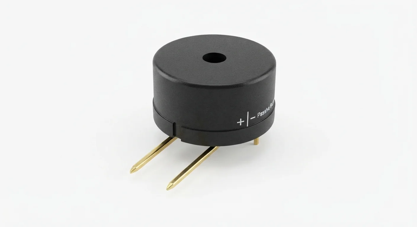
- A two-terminal external-drive piezo sounder rated for a 0–3.3 V square-wave drive, with its manufacturer-approved drive circuit. The illustration's passive label does not prove piezo construction, resonance or current. A magnetic sounder needs a separate documented driver and inductive protection.
- Prerequisites and parts
- Complete IDE setup. Qualified piezo sounder, known 1 kiloohm series resistor, wires and breadboard. Check the actual sounder's permitted voltage, frequency and driver requirements.
- Expected result
- A 2 kHz tone lasts 250 ms, followed by silence for one second. Serial prints TONE and SILENT. Volume depends on the sounder and the series resistor.
- Verification limits
- Documentation and automated content/browser checks only in this update. No ESP32 compilation or physical hardware testing. The approved image depicts a component family; it does not authenticate a model, rating or terminal order.
Overview
A passive sounder needs an alternating drive waveform. An active buzzer contains an oscillator and can sound from DC. Neither its round case nor a plus mark identifies its internal construction.
The example deliberately supports only an external-drive piezo qualified for this circuit. Do not connect an unknown magnetic coil, speaker or active module directly to the GPIO. The approved illustration is a category image, not a verified electrical model.
Technical Specifications
Arduino library: Arduino-ESP32 3.x; no additional library
| Specification | Value | Why it matters |
|---|---|---|
| Supported construction | External-drive piezo only | Magnetic sounders and active buzzers require different interfaces. |
| Example tone | 2 kHz for 250 ms | Software choice, not a claimed resonance or measured loudness. |
| Signal resistor | 1 kiloohm | Limits GPIO charging pulses and reduces volume; verify actual drive requirements. |
| Supply in this example | Piezo receives only the GPIO25 waveform through 1 kiloohm; no external power rail in this example. | Applies only to the supported hardware assumptions above. |
| ESP32 signal compatibility | LEDC produces a 0–3.3 V, 50% duty waveform. GPIO is LOW during silence. | Applies only to the supported hardware assumptions above. |
| Required protection | The 1 kiloohm series resistor limits edge/short-circuit current to about 3.3 mA at 3.3 V. It does not make an unknown magnetic load suitable or replace a manufacturer drive circuit. | Applies only to the supported hardware assumptions above. |
Pinout
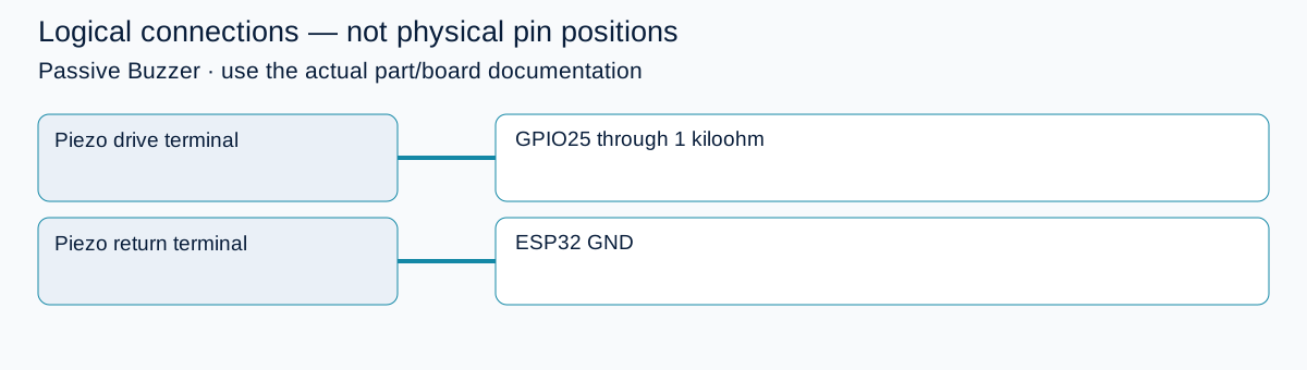
- Piezo drive terminal Use the actual documented drive terminal; artwork is not pin identification. GPIO25 through 1 kiloohm Use the actual documented drive terminal; artwork is not pin identification.
- Piezo return terminal Follow manufacturer polarity/drive instructions if present. ESP32 GND Follow manufacturer polarity/drive instructions if present.
Wiring Diagram
Qualified piezo drive terminal → 1 kiloohm → GPIO25; return → GND. No magnetic or active sounder substitution.
| Identified terminal | Connection | Qualification |
|---|---|---|
| Piezo drive terminal | GPIO25 through 1 kiloohm | Use the actual documented drive terminal; artwork is not pin identification. |
| Piezo return terminal | ESP32 GND | Follow manufacturer polarity/drive instructions if present. |
Open wiring diagram at full size (new tab)
-
1
Disconnect power and confirm external-drive piezo construction and permitted waveform.
-
2
Wire the series resistor and common return; keep sounder away from ears.
-
3
Upload and open Serial Monitor; if silent, verify construction and frequency requirements before changing the circuit.
Wiring and matching Arduino code
Short tone with pin-based LEDC
Qualified piezo drive terminal → 1 kiloohm → GPIO25; return → GND. No magnetic or active sounder substitution.
passive_buzzer_esp32.ino
#include <Arduino.h>
constexpr uint8_t BUZZER_PIN = 25;
bool ready = false;
void setup() {
  Serial.begin(115200);
  pinMode(BUZZER_PIN, OUTPUT);
  digitalWrite(BUZZER_PIN, LOW);
  ready = ledcAttach(BUZZER_PIN, 2000, 8);
  if (!ready) Serial.println("LEDC attach failed; check board and resources.");
}
void loop() {
  if (!ready) { delay(1000); return; }
  if (ledcWriteTone(BUZZER_PIN, 2000) == 0) {
    ledcWriteTone(BUZZER_PIN, 0);
    Serial.println("Tone setup failed.");
    delay(1000);
    return;
  }
  Serial.println("TONE");
  delay(250);
  ledcWriteTone(BUZZER_PIN, 0);
  Serial.println("SILENT");
  delay(1000);
}
Arduino-ESP32 3.x APIs take the pin, not an old channel number. No tone library required. Zero frequency sets duty to zero; sounder ratings must be checked separately.
Expected Output
A 2 kHz tone lasts 250 ms, followed by silence for one second. Serial prints TONE and SILENT. Volume depends on the sounder and the series resistor.
How it works
The LEDC peripheral toggles the output at the selected frequency; tone generation continues during delay. Setting frequency to zero stops the drive. Resonance affects acoustic output, so a working Serial message is not proof that the sounder is suitable or audible. A series resistor trades volume for lower GPIO charging current.
Troubleshooting
| Problem | Possible cause | Solution |
|---|---|---|
| Serial works but no sound | Wrong sounder type, unsuitable frequency or wiring. | Confirm an external-drive piezo and its data. Check GPIO25 and ground; do not bypass protection on an unknown load. |
| Sound pitch does not change | An active buzzer may have its own oscillator. | Identify the actual part; active-buzzer control is a different example. |
| LEDC attach fails | Wrong core/board or peripheral resources occupied. | Use Arduino-ESP32 3.x, a valid unused output pin and the standalone sketch. |
Where you use it
- Short status tone
- Digital piano preparation
- Low-volume user feedback
Continue learning
Related projects
FAQ
No. Its coil current and inductive switching require a selected transistor/driver and appropriate protection. This illustration does not establish that interface.
An external-drive piezo needs a changing waveform for a sustained tone. DC is not the provided operating mode.
Technical references
- Espressif GPIO API — Pin modes and digital output on Arduino-ESP32.
- Murata piezoelectric sound components — Manufacturer guidance on external versus self-drive sounders; not a model identification.
- Espressif LEDC API — ledcAttach, pin-based ledcWriteTone and zero-frequency behavior.