
Before you start
- Board and software
- Classic ESP32-WROOM-32/32E DevKit with the listed GPIOs exposed and unused. Arduino IDE 2.x; esp32 by Espressif Systems 3.3.2 (review baseline, not a latest-release claim). Select the documented board or ESP32 Dev Module for a generic WROOM board. Other families need their own pin map. Serial Monitor: 115200 baud.
- Supported hardware
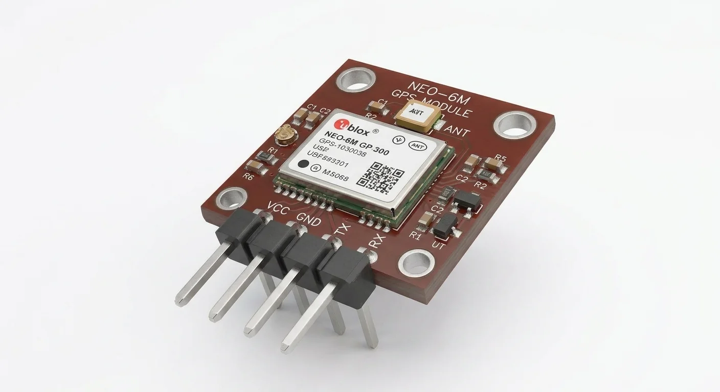
- Documented NEO-6M carrier with a 3.3 V-compatible supply input and native 3.3 V UART TX, configured for default 9600 8N1 NMEA output. Check carrier regulator/input requirements and antenna before wiring; the illustration cannot identify a revision or authentic silicon. Not a NEO-6G or an RS-232 output.
- Prerequisites and parts
- IDE setup first. Documented compatible antenna/carrier, short wires and a regulated external 3.3 V source with budget for receiver, carrier and antenna. GPS TX → GPIO16, shared ground. WROOM GPIO16/17 must be exposed and unused; PSRAM boards can reserve them. ESP32 stays on USB.
- Libraries
- Arduino-ESP32 3.3.2 built-in HardwareSerial; no NMEA parsing library required.
- Expected result
- Serial Monitor at 115200 shows receiver bytes; readable NMEA may be emitted even when there is no valid position fix.
- Verification status
- Documentation and source review only. Not compiled or tested on hardware. The approved product-style illustration identifies a family, not a verified physical pin layout or manufacturer-authenticated board. Follow the logical diagram and documentation for your actual part.
Overview
A GPS receiver computes a position from satellite signals and sends status over UART. Start by reading that stream before adding a parser or a map: this separates wiring and baud problems from sky-view problems.
NEO-6M is a GPS receiver family, not a guarantee about a generic breakout’s voltage input. The module itself operates from 2.7–3.6 V; a carrier may put a regulator between its header and the receiver. This worked connection requires a header documented for 3.3 V input. Do not blindly apply 5 V to the module or assume 3.3 V reaches it through every carrier regulator.
Technical Specifications
Arduino library: Arduino-ESP32 3.3.2 built-in HardwareSerial; no extra library.
| Specification | Value | Why it matters |
|---|---|---|
| Receiver identity | NEO-6M; UART NMEA demonstration | Different families/configurations need their own documentation. |
| Receiver supply versus carrier | Module 2.7–3.6 V; worked header 3.3 V | Carrier regulators can require different header voltages. |
| UART setup | 9600 baud, 8N1 | Default NEO-6 settings; saved/custom settings may differ. |
| Host Serial Monitor | 115200 baud | Independent of receiver-side UART baud. |
Pinout
- GPS documented 3.3 V input Supply External regulated 3.3 V Check actual carrier input and current/antenna budget.
- GPS GND / supply minus Reference ESP32 GND Keep positive rails separate.
- GPS TXD / TX UART output GPIO16 (ESP32 RX) Verify 3.3 V TTL; follow labels, not pin order.
- GPS RXD / RX UART input Leave disconnected No receiver commands in this read-only exercise.
- ESP32 GPIO17 UART TX Leave disconnected Explicit Serial2 TX assignment; not wired to GPS.
- GPS antenna connector RF Documented compatible antenna No antenna pin guessing from artwork.
Wiring Diagram
GPS TX → GPIO16, common GND. Separate documented 3.3 V GPS supply; ESP32 USB. GPS RX and GPIO17 unwired.
| Component terminal | ESP32 / circuit connection | Purpose and qualification |
|---|---|---|
| GPS documented 3.3 V input | External regulated 3.3 V | Check actual carrier input and current/antenna budget. |
| GPS GND / supply minus | ESP32 GND | Keep positive rails separate. |
| GPS TXD / TX | GPIO16 (ESP32 RX) | Verify 3.3 V TTL; follow labels, not pin order. |
| GPS RXD / RX | Leave disconnected | No receiver commands in this read-only exercise. |
| ESP32 GPIO17 | Leave disconnected | Explicit Serial2 TX assignment; not wired to GPS. |
| GPS antenna connector | Documented compatible antenna | No antenna pin guessing from artwork. |
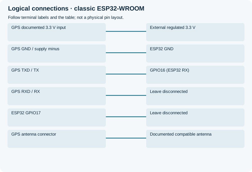
Open wiring diagram at full size (new tab)
-
1
Verify actual carrier power input, TTL signal and antenna documentation, then disconnect supplies before wiring.
-
2
Upload and open Serial Monitor at 115200. GPS side starts at 9600 8N1; correct only if the receiver is documented at another baud.
-
3
Place the matched antenna with unobstructed sky view without touching RF contacts. Inspect sentence validity separately from whether bytes arrive.
Wiring and matching Arduino code
Read-only receiver UART bridge
GPS TX → GPIO16, common GND. Separate documented 3.3 V GPS supply; ESP32 USB. GPS RX and GPIO17 unwired.
neo_6m_gps.ino
#include <Arduino.h>
constexpr int8_t GPS_RX = 16;
constexpr int8_t UNUSED_TX = 17;
uint32_t bytesSeen = 0;
uint32_t lastCheck = 0;
void setup() {
  Serial.begin(115200);
  Serial2.begin(9600, SERIAL_8N1, GPS_RX, UNUSED_TX);
  Serial.println("GPS TX -> GPIO16; Monitor 115200, GPS 9600.");
}
void loop() {
  for (uint8_t n = 0; n < 64 && Serial2.available() > 0; ++n) {
    const int value = Serial2.read();
    if (value >= 0) {
      Serial.write(static_cast<uint8_t>(value));
      ++bytesSeen;
    }
  }
  const uint32_t now = millis();
  if (now - lastCheck >= 5000) {
    lastCheck = now;
    if (bytesSeen == 0) Serial.println("No UART bytes: check power, RX wiring and baud.");
    bytesSeen = 0;
  }
  delay(1);
}
A bounded receive loop and five-second no-byte diagnostic; no blocking wait for satellites. Does not parse/validate checksums, coordinates or a fix. No commands sent; attach a version-pinned parser with validation before using coordinates in an application.
Expected Output
Expect lines beginning with sentence identifiers such as $GPRMC or $GPGGA for default NMEA output. No fix is still compatible with readable sentences. Receiver configurations can change talker IDs/messages; this sketch makes no location or accuracy assertion.
How it works
The two UARTs have different baud rates: the receiver sends slowly to Serial2 while the USB debugging port prints at 115200. The program forwards bytes only, so corrupt data is not silently converted into plausible coordinates.
For NMEA navigation, inspect RMC status (A valid / V void) and GGA fix-quality (0 means no fix) with checksum validation in a parser. Latitude/longitude fields use degrees and minutes, not ready-made decimal degrees. A first-byte check is a communications check; it is not a satellite-fix test.
Troubleshooting
| Problem | Possible cause | Solution |
|---|---|---|
| No bytes | Wrong RX pin, missing supply/ground or disabled UART output. | Check the actual header voltage, GPS TX to GPIO16 and receiver configuration; sky view alone does not fix a silent UART. |
| Unreadable characters | Wrong GPS baud/protocol or signal level. | Keep Monitor at 115200; verify receiver baud separately. UBX binary output will not look like NMEA text. |
| Sentences but no fix | Poor antenna/sky view, startup acquisition or receiver configuration. | Use a documented antenna and open sky; check status with validation. Do not promise a universal acquisition time. |
| Works on one board only | GPIO16/17 reserved or board family differs. | Use the stated WROOM map; choose available UART pins from the actual board documentation. |
Where you use it
- UART bring-up before adding a NMEA parser
- Learning the difference between serial output and navigation validity
Continue learning
FAQ
Only if its carrier documentation permits that supply and confirms ESP32-safe UART levels. That is a different supply connection from this worked 3.3 V example.
No. A parser must check status, age and checksum; old or invalid fields must not be treated as a current position.
Technical references
- u-blox NEO-6 datasheet — NEO-6M module operating conditions, UART levels/default settings; not identification of an unknown carrier.
- u-blox 6 receiver protocol specification — NMEA RMC/GGA fields and validity; no parser library used.
- Arduino-ESP32 3.3.2 HardwareSerial — Pinned begin/read/write APIs and explicit RX/TX assignment.