
Plain-English Overview
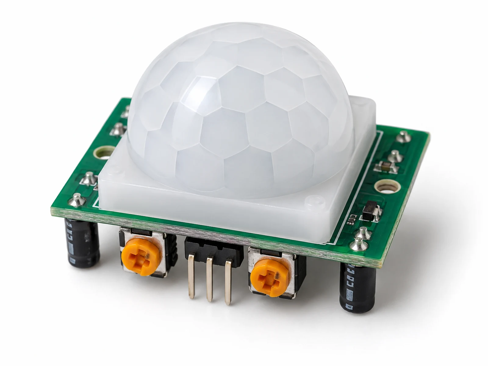
A PIR sensor watches for changes in heat. People, pets, and warm objects give off infrared energy. When a warm body moves across the sensor view, the module notices the change and sends a signal to the ESP32.
It does not see pictures like a camera. It only tells your board that motion happened. That makes it useful for simple alarms, lights, and wake-up triggers without recording anyone.
Use it when you care about movement, not exact distance or identity.
Where You Use It
- Motion security alert
- Automatic light trigger
- Occupancy sensing
- Visitor counter experiment
- Wake-up trigger for battery nodes
- Classroom infrared demo
- Smart hallway light
- Camera trap trigger
Quick Facts
- Detects Moving warm bodies
- Output Digital HIGH/LOW
- Power Usually 5 V module input
- Warm-up 30-60 seconds
- Adjustments Sensitivity and delay trimpots
- Best use Motion trigger
How It Works
PIR means passive infrared. Passive means the sensor does not send energy out like an ultrasonic sensor. It only observes infrared energy already coming from objects.
The white dome is a Fresnel lens. It splits the room into zones and focuses infrared energy onto two sensing elements. When a warm body moves from one zone to another, the two elements see a changing heat pattern.
The module amplifies that tiny change and turns it into a digital output. HIGH means motion was detected. LOW means no recent motion. The onboard delay control decides how long the output stays HIGH after motion.
Because PIR detects change, a person standing perfectly still may stop triggering it. Heat sources, sunlight, HVAC airflow, and pets can also trigger it if the sensor points at them.
Technical Specifications
Arduino library: Built-in Arduino digitalRead
| Specification | Value | Why it matters |
|---|---|---|
| Supply voltage | Typically 5 V to 20 V module input | Common HC-SR501 boards include regulation; use module documentation. |
| Output logic | Digital HIGH on motion | ESP32 can read the OUT pin as a digital input. |
| Output voltage | Often about 3.3 V HIGH | Usually ESP32-safe, but verify your module if uncertain. |
| Detection range | Up to about 7 m | Depends on sensitivity setting, lens, target size, and environment. |
| Field of view | Roughly 100 degrees | Wide coverage but not precise direction sensing. |
| Warm-up time | 30-60 seconds | Readings can be unstable immediately after power-up. |
| Delay time | Adjustable, often seconds to minutes | Controls how long OUT remains HIGH after motion. |
| Sensitivity | Adjustable by trimpot | Helps reduce false triggers or extend range. |
| Trigger mode | Repeatable or non-repeatable on some modules | Jumper behavior changes output timing. |
| Best targets | Moving warm bodies | The sensor responds to infrared change, not visible motion. |
Pinout
- VCC Module power 5 V typical Powers the PIR module and onboard regulator.
- OUT Digital motion output ESP32 GPIO27 Usually HIGH when motion is detected.
- GND Ground reference ESP32 GND Required for ESP32 to read OUT correctly.
- Delay trimpot Output hold adjustment Turn gently with small screwdriver Changes how long OUT stays HIGH.
- Sensitivity trimpot Range adjustment Turn gently with small screwdriver Changes detection range and false trigger tendency.
Wiring Diagram
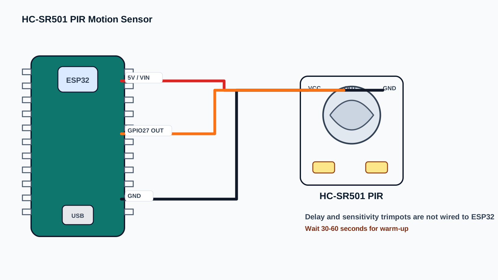
The HC-SR501 PIR module has a control side only: VCC, OUT, and GND. OUT is a digital signal the ESP32 reads on GPIO27 in this site's motion examples.
After powering the sensor, wait at least 30 seconds before judging behavior. During warm-up, random triggers are normal. Module variants differ, so verify your board labels, trimpot direction, jumper mode, and OUT voltage if uncertain.
| PIR Pin | ESP32 Connection | Purpose / Notes |
|---|---|---|
| VCC | 5 V / VIN typical | Common HC-SR501 modules usually use 5 V module input. Follow your module label and documentation. |
| GND | GND | Shared ground lets the ESP32 read the OUT signal correctly. |
| OUT | GPIO27 | Digital motion signal. Usually HIGH when motion is detected and LOW after the hold delay clears. |
| Delay trimpot | Not wired to ESP32 | Adjusts how long OUT remains HIGH after motion on common HC-SR501 modules. |
| Sensitivity trimpot | Not wired to ESP32 | Adjusts detection range and false-trigger tendency; turn gently. |
-
1
Unplug USB before wiring.
-
2
Connect PIR VCC to 5 V or VIN on the ESP32 board.
-
3
Connect PIR GND to ESP32 GND.
-
4
Connect PIR OUT to ESP32 GPIO27.
-
5
Point the dome away from windows, heaters, and moving fans.
-
6
Power the ESP32 and wait 30-60 seconds for warm-up.
-
7
Open Serial Monitor at 115200 baud.
-
8
Walk across the sensor view and watch for motion messages.
Code Examples
Use the same wiring with Arduino IDE, PlatformIO, or ESP-IDF. Start with Arduino, then graduate when you need a larger project structure.
#define PIR_PIN 27

int lastState = LOW;

void setup() {
  Serial.begin(115200);
  pinMode(PIR_PIN, INPUT);
  Serial.println("PIR motion sensor warming up...");
  delay(30000);
  Serial.println("PIR ready. Walk across the sensor view.");
}

void loop() {
  int currentState = digitalRead(PIR_PIN);

  if (currentState != lastState) {
    if (currentState == HIGH) {
      Serial.println("Motion detected");
    } else {
      Serial.println("Motion cleared");
    }
    lastState = currentState;
  }

  delay(100);
}#include <Arduino.h>
#define PIR_PIN 27
int lastState = LOW;
void setup() {
Serial.begin(115200);
pinMode(PIR_PIN, INPUT);
Serial.println("PIR motion sensor warming up...");
delay(30000);
Serial.println("PIR ready. Walk across the sensor view.");
}
void loop() {
int currentState = digitalRead(PIR_PIN);
if (currentState != lastState) {
if (currentState == HIGH) {
Serial.println("Motion detected");
} else {
Serial.println("Motion cleared");
}
lastState = currentState;
}
delay(100);
}// ESP-IDF starter structure for this component.
// Keep the wiring from the pinout section, then move the read/write logic into app_main().
#include <stdio.h>
#include "freertos/FreeRTOS.h"
#include "freertos/task.h"
void app_main(void) {
printf("HC-SR501 PIR Motion Sensor ready\n");
while (true) {
// Add component read/write code here.
vTaskDelay(pdMS_TO_TICKS(1000));
}
}The PIR output is digital, so no special library is needed. The code watches for state changes instead of printing continuously.
setup() gives the sensor time to stabilize. loop() compares the current reading with the previous reading, then prints only when motion starts or clears. This keeps Serial Monitor readable.
Expected Output
After a warm-up message and 30 second delay, Serial Monitor prints Motion detected when someone moves across the sensor view. Depending on the delay trimpot, it may print Motion cleared several seconds later. If it triggers while nobody is moving, check heat sources and sensitivity.
Common Mistakes
- Judging the sensor during warm-up.
- Pointing it at windows or sunlight.
- Pointing it at heaters, vents, or fans.
- Expecting it to detect still people.
- Using it as a distance sensor.
- Forgetting common ground.
- Turning trimpots aggressively.
- Mounting behind glass or thick plastic.
- Using delay setting without understanding hold time.
- Printing continuously instead of detecting state changes.
Troubleshooting
| Problem | Possible cause | Solution |
|---|---|---|
| Triggers randomly | Heat source, sunlight, HVAC airflow, pets, or high sensitivity. | Point away from heat changes and reduce sensitivity. |
| Never triggers | No power, wrong OUT pin, still target, or sensor blocked. | Check wiring, wait for warm-up, and walk across the lens. |
| Always HIGH | Delay setting high, retrigger mode, or constant motion/heat. | Wait for timeout, reduce delay, and move away from heat sources. |
| Always LOW | Power missing or OUT not connected to the coded GPIO. | Confirm VCC, GND, GPIO27, and Serial output. |
| Works only sometimes | Target movement direction or range is poor. | Walk across the field of view, not straight toward the sensor. |
| Triggers through window | Sunlight/heat changes affect the sensor. | Avoid aiming at windows. |
| Does not detect through glass | Glass blocks much infrared energy. | Mount with clear view of the room. |
| Motion cleared takes too long | Delay trimpot set high. | Turn delay adjustment lower carefully. |
| Range too short | Sensitivity low or lens obstructed. | Increase sensitivity and check dome orientation. |
| Pets trigger it | PIR sees warm moving animals. | Aim higher or mask part of the lens. |
| ESP32 reads unstable | Floating input or poor ground. | Use common ground and stable wiring. |
| False trigger when relay switches | Electrical noise or power dip. | Separate relay power and add filtering. |
| No output after boot | Warm-up period not complete. | Wait 30-60 seconds. |
| Board resets | Weak power supply. | Use stable USB power. |
| Cannot tell direction | PIR only gives motion/no motion. | Use multiple sensors or another technology for direction. |
Related Guides
Related Projects
FAQ
It detects changes in infrared heat caused by moving warm bodies.
No. It only outputs motion/no motion.
Not reliably. PIR detects changes, so still people may disappear.
Most HC-SR501 modules use 5 V input.
Most modules output about 3.3 V, but verify your module if uncertain.
GPIO27 is a good beginner input pin.
The sensor amplifier needs time to stabilize.
One adjusts sensitivity/range and the other adjusts output hold delay.
Sometimes, but sunlight, temperature changes, and weather cause false triggers.
Usually poorly because glass blocks or changes infrared energy.
Yes, warm moving pets can trigger it.
Up to about 7 m under good conditions.
Heat movement from windows, vents, heaters, pets, or high sensitivity.
No. Use HC-SR04 or another distance sensor.
Yes, but polling is easier for beginners.
A jumper mode where motion can extend the HIGH output while movement continues.
Yes, with suitable wiring to a wake-capable pin and low-power design.
The delay trimpot holds output HIGH for the set time.
Yes, use separate GPIOs or combine signals carefully.
It is more privacy friendly than a camera because it does not capture images.
Passive infrared means the module senses changes in heat energy from objects; it does not shine a beam.
Hold delay is how long the OUT pin stays HIGH after motion is detected.
Use a low-voltage LED or Serial Monitor test indoors before connecting alarms, relays, or network alerts.
Pets, heaters, windows, vents, and sunlight can all create motion-like heat changes.
It teaches digital inputs, warm-up time, false positives, and the difference between detection and measurement.
Have students record jumper mode, delay setting, sensitivity setting, room conditions, and trigger observations.
Lower sensitivity, move the module away from heat sources, and test one change at a time.
Trigger a local light or message first, then add privacy-friendly logging only when the test is stable.
No. PIR reports motion/no motion; use HC-SR04 for distance.
The amplifier needs time to stabilize before the first readings are trustworthy.
HC-SR501 PIR Motion Sensor is a input devices part used with the ESP32. Learn its job first, then connect power, ground, and signal pins exactly as the wiring table shows.
A signal pin is the wire that carries information between the ESP32 and the component. It may be digital, analog, I2C, SPI, PWM, or another protocol depending on the part.
For a beginner ESP32 lesson, this component is suitable when an adult checks the wiring, keeps the project at low voltage, and unplugs USB before moving jumper wires.
Watch for reversed power pins, loose jumper wires, and children touching the circuit while it is powered. Most beginner ESP32 mistakes are wiring mistakes, not broken parts.
Use HC-SR501 PIR Motion Sensor to connect one visible hardware behavior to one software concept. Ask students to predict the reading or output first, then test it on real hardware.
Assess whether students can explain the wiring, identify the ESP32 pins used, run the example, describe the expected output, and troubleshoot one intentional mistake.
Change one variable at a time: move to another valid GPIO, adjust the timing, display the value on an OLED, or combine the component with a related project.
Disconnect one wire, predict the failure, observe the output, then explain why the failure happened before reconnecting the circuit.
Unplug USB power first. Then check the pin labels, voltage level, and ground connection before powering the ESP32 again.
Common ground gives the ESP32 and the component the same voltage reference. Without it, signal readings can be wrong or unstable.
Review, Testing, and References
Author: Abdul Mubeen and the ESP32 Engine editorial team. Last updated: 2026-08-22. Reviewed: wiring, code, beginner safety, and ESP32 compatibility. Educational level: Beginner.
Use this component page as an educational starting point. Check official documentation before using the part in production, high-current, outdoor, battery, or safety-critical hardware.
Downloads
HC-SR501 module references vary by manufacturer. Check your module markings, jumper mode, delay range, and sensitivity trimpot direction.
Download Datasheet (PDF)