
Before you start
- Board and software
- Classic ESP32-WROOM-32/32E DevKit with these GPIOs exposed and unused. Arduino IDE 2.x; esp32 by Espressif Systems 3.x (API review baseline 3.3.2, not a latest-version claim). Select the exact board or ESP32 Dev Module for a generic WROOM board. Other ESP32 families need their own pin map. Serial Monitor: 115200 baud.
- Hardware assumption
- A positional SG90-class servo documented for 4.8 V supply and a 50 Hz RC control signal accepting 1400–1600 µs pulses. Tower Pro lists 4.8 V for its SG90 Digital; clones/different revisions are not assumed identical. Use a standard 14-pin SN74AHCT125 powered from the same regulated 4.8 V rail.
- Prerequisites and parts
- First complete Arduino IDE setup and Blink. Servo without mechanical load, regulated external 4.8 V supply sized for its actual starting/stall current, SN74AHCT125, 100 nF buffer decoupling and suitable supply wiring.
- Expected result
- The servo starts near its pulse-defined center, then alternates between two nearby positions. No angle, torque or travel is promised for an unidentified variant.
- Verification status
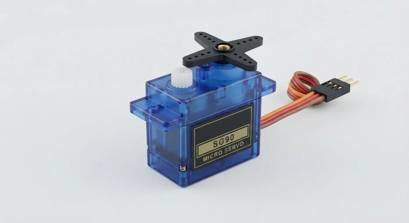
- Reviewed against the technical references below. Not compiled for an ESP32 or tested on hardware in this update. The approved product-style illustration identifies the family; follow documented terminal labels and the logical wiring diagram, not its rendered pin positions.
Overview
A positional servo uses repeated control pulses to choose a position; it is not powered from the signal wire. The motor can draw a surge when starting or blocked, so its supply must be independent of the ESP32 3.3 V rail.
Tower Pro lists 4.8 V and external adapter power for its SG90 Digital. This example uses that nominal rail; do not infer a universal 5–6 V rating from the SG90 name. A 5 V supply is acceptable only if the exact servo documentation permits it. Share ground with the USB-powered ESP32, not independent positive rails.
Technical Specifications
Arduino library: No additional servo library; Arduino-ESP32 3.x LEDC API
| Specification | Value | Why it matters |
|---|---|---|
| Servo type | Positional SG90-class | Continuous-rotation conversions behave differently; no universal travel/torque claim. |
| Power | Documented external 4.8 V supply | Size for actual peak/stall current; stop if buzzing or blocked. |
| Control | 50 Hz (20 ms period) | Assumed standard RC positional control; verify actual servo. |
| Example pulse width | 1500 µs start; 1400 / 1600 µs movement | Small initial range, not universal angles or endpoints. |
| LEDC | GPIO25, 16-bit resolution on classic ESP32 | Uses ledcAttach and pin-based ledcWrite in Arduino-ESP32 3.x; other families may have lower resolution limits. |
Pinout
- Servo positive Motor/electronics supply External regulated 4.8 V Common red convention is not proof: verify connector wiring.
- Servo ground Return Supply minus + ESP32 GND + buffer pin7 Use supply wiring sized for motor current; no motor current through GPIO.
- Servo signal RC pulse input GPIO25 → buffer 1A pin2 / 1Y pin3 → signal Buffer VCC pin14 to 4.8 V; OE pin1 LOW; 100 nF between supply/ground.
- Unused buffer channels Defined unused state OE pins4/10/13 HIGH; A pins5/9/12 LOW Outputs6/8/11 unconnected; verify standard 14-pin package. Do not substitute plain HC125 without checking input thresholds.
Wiring Diagram
External regulated 4.8 V powers the documented servo and SN74AHCT125; all grounds join. GPIO25 controls buffer channel1, whose output drives the identified servo signal lead.
| Component terminal | ESP32 / circuit connection | Purpose and qualification |
|---|---|---|
| Servo positive | External regulated 4.8 V | Common red convention is not proof: verify connector wiring. |
| Servo ground | Supply minus + ESP32 GND + buffer pin7 | Use supply wiring sized for motor current; no motor current through GPIO. |
| Servo signal | GPIO25 → buffer 1A pin2 / 1Y pin3 → signal | Buffer VCC pin14 to 4.8 V; OE pin1 LOW; 100 nF between supply/ground. |
| Unused buffer channels | OE pins4/10/13 HIGH; A pins5/9/12 LOW | Outputs6/8/11 unconnected; verify standard 14-pin package. Do not substitute plain HC125 without checking input thresholds. |
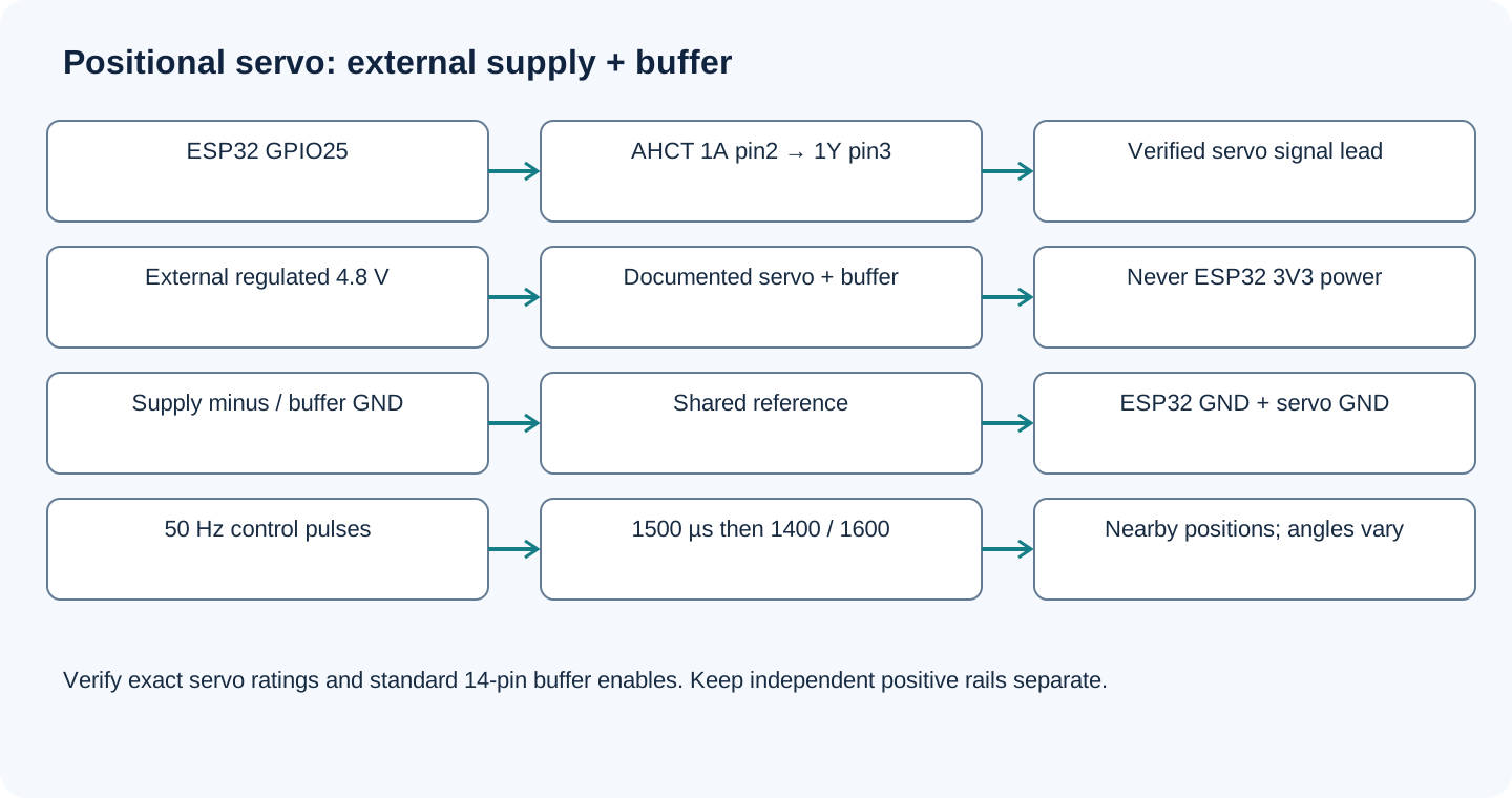
Open wiring diagram at full size (new tab)
-
1
Disconnect USB and servo power. Verify the exact servo supply range, signal lead and allowed pulses. Remove the horn/load for first movement.
-
2
Wire buffer channel1, enables, decoupling and unused inputs as shown. Share ground but do not join external positive to USB/3V3.
-
3
Upload the sketch with Arduino-ESP32 3.x, then power the verified servo circuit. Keep fingers and loose wires away from motion.
-
4
Start with the narrow pulse range. Disconnect power if the servo strains; do not force the shaft or widen endpoints blindly.
Wiring and matching Arduino code
Narrow-range positional pulse test
External regulated 4.8 V powers the documented servo and SN74AHCT125; all grounds join. GPIO25 controls buffer channel1, whose output drives the identified servo signal lead.
sg90_micro_servo_esp32.ino
#include <Arduino.h>
constexpr uint8_t SERVO_PIN = 25;
constexpr uint8_t RESOLUTION = 16; // Classic ESP32 supports this at 50 Hz.
constexpr uint32_t PERIOD_US = 20000;
bool ready = false;
bool nextHigh = false;
bool writePulse(uint32_t pulseUs) {
  uint32_t duty = (pulseUs * (1UL << RESOLUTION) + PERIOD_US / 2) / PERIOD_US;
  return ledcWrite(SERVO_PIN, duty); // 3.x uses the pin, not a channel number.
}
void setup() {
  Serial.begin(115200);
  ready = ledcAttach(SERVO_PIN, 50, RESOLUTION);
  if (ready) ready = writePulse(1500);
  if (!ready) { Serial.println("LEDC configuration failed."); return; }
  Serial.println("Start at 1500 us; next pulses are 1400 and 1600 us.");
  delay(2000);
}
void loop() {
  if (!ready) { delay(1000); return; }
  uint32_t pulseUs = nextHigh ? 1600 : 1400;
  nextHigh = !nextHigh;
  ready = writePulse(pulseUs);
  if (!ready) { Serial.println("LEDC write failed."); return; }
  Serial.printf("Pulse: %lu us\n", static_cast<unsigned long>(pulseUs));
  delay(2000);
}
Pulse duty equals pulse duration divided by the 20 ms period, scaled to 2^16. Hardware LEDC maintains pulses during delay(). This is positional control, not speed control; a successful API return does not verify a connected servo.
Expected Output
After the initial 1500 µs pulse, the sketch sends 1400 and 1600 µs alternately every two seconds. A compatible unloaded positional servo should move between nearby positions. Exact angles depend on the model; continuous rotation, buzzing, hard stops or resets call for stopping and checking hardware.
How it works
Pulse width requests position. Increasing supply voltage does not select an angle. The buffer provides a documented logic interface instead of assuming every servo accepts ESP32 3.3 V HIGH. External supply capacity and a common reference remain necessary even when code and pulse timing are correct.
Troubleshooting
| Problem | Possible cause | Solution |
|---|---|---|
| ESP32 resets when the servo moves | Supply droop or motor current in ESP32 power wiring. | Use separate rated servo power and common ground; check actual surge current, wiring and supply decoupling. |
| No movement | Wrong connector, disabled buffer, unsupported pulse input or no servo power. | Check vendor lead order, 4.8 V-compatible supply, shared ground, buffer OE and pulses; USB alone is not servo power. |
| Buzzing or hard stop | Load, mechanical obstruction or unsuitable pulse range. | Disconnect power, remove the load and verify the model/pulse range. Do not force the shaft. |
| ledcAttach is missing | Arduino-ESP32 2.x or wrong board/core. | Select Arduino-ESP32 3.x and the classic WROOM board. Do not mix channel-based legacy calls with this pin-based example. |
Where you use it
- Small indicator pointer
- Unloaded servo learning experiment
- Documented low-load robot joint
Continue learning
Related projects
FAQ
No in this build. Use an external supply documented for the exact servo and sized for motor surges; share only the required ground reference.
No such blanket claim is made. Tower Pro’s referenced SG90 Digital page lists 4.8 V; the exact servo/revision controls your supply choice.
Not for every variant. It is a conventional starting pulse, not a verified angle; check the actual servo documentation and mechanical range.
Technical references
- Tower Pro SG90 Digital — Manufacturer lists 4.8 V and external adapter supply for this product; not a guarantee for clones.
- Adafruit RC servo guide — RC pulse width versus positional/continuous-rotation behavior.
- TI SN74AHCT125 datasheet — 4.5–5.5 V supply, TTL inputs, enables and package pinout.
- Espressif LEDC API — 3.x pin-based ledcAttach/ledcWrite and classic ESP32 resolution limits.
Downloads
Official manufacturer PDF for teachers and advanced builders.
No separate datasheet is needed for this beginner guide.