
Before you start
- Board and software
- Classic ESP32-WROOM-32/32E DevKit with the listed GPIOs exposed and unused. Arduino IDE 2.x; esp32 by Espressif Systems 3.3.2 (review baseline, not a latest-release claim). Select the documented board or ESP32 Dev Module for a generic WROOM board. Other families need their own pin map. Serial Monitor: 115200 baud.
- Supported hardware
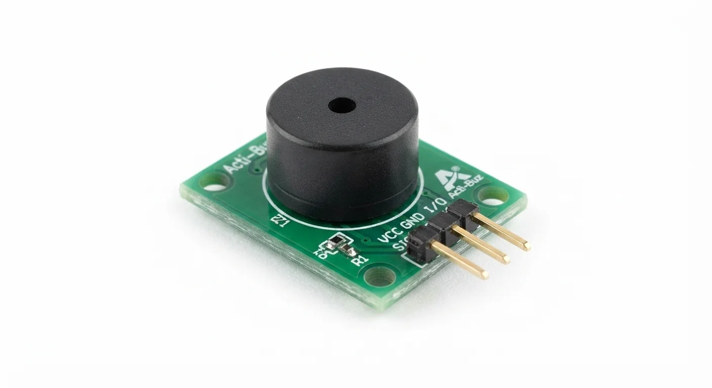
- Worked reference: Joy-IT COM-KY012APB / KY-012 as documented in its May 2024 manual: voltage between S (powered terminal) and GND makes sound; middle pin is not connected. The generic approved module illustration is not identified as this product. Do not transplant this wiring to a VCC/GND/IN board without its schematic.
- Prerequisites and parts
- Complete Blink and the NPN switching lesson. Documented Joy-IT module, onsemi P2N2222A, 680 ohm base resistor, 100 kOhm base-emitter pull-down, short wires and a regulated 5 V supply rated for the documented module current. ESP32 remains USB powered; join grounds, not positive rails.
- Libraries
- No extra library. Arduino-ESP32 3.3.2 GPIO and millis APIs.
- Expected result
- A fixed-pitch beep for 200 ms followed by 1800 ms silence. The sketch controls the envelope, not pitch.
- Verification status
- Documentation and source review only. Not compiled or tested on hardware. The approved product-style illustration identifies a family, not a verified physical pin layout or manufacturer-authenticated board. Follow the logical diagram and documentation for your actual part.
Overview
An active buzzer contains an oscillator, so steady power produces a tone. Turn that power on and off to make alert patterns. A passive buzzer instead needs an alternating drive signal and can play different pitches. The approved image depicts an active-module family but cannot verify a real unit’s oscillator or trigger polarity.
The reference KY-012 terminal S carries buzzer power, not just a logic command. Use the transistor below instead of drawing buzzer current from ESP32 GPIO. Other active modules may have separate VCC and IN, active-LOW control or different ratings.
Technical Specifications
Arduino library: Arduino-ESP32 3.3.2 (no additional library)
| Specification | Value | Why it matters |
|---|---|---|
| Reference interface | S powered terminal, GND return, middle NC | Not a universal VCC/GND/IN connector. |
| Reference current budget | Up to 30 mA per Joy-IT sensor documentation | Check the purchased product revision and supply; no current measured here. |
| Base resistor | 680 ohm with P2N2222A | About 3.7 mA for a 0.8 V base-emitter estimate; sized separately from the LED lesson. |
Pinout
- KY-012 S Power External regulated +5 V Powered buzzer terminal, not GPIO.
- KY-012 GND / minus Switched return P2N2222A pin1 collector Do not also connect this terminal directly to ground.
- KY-012 middle pin NC Not connected Reference manual only; not generic module order.
- P2N2222A pin3 emitter Return Common GND External supply negative and ESP32 GND.
- P2N2222A pin2 base Control GPIO25 through 680 ohm Verify exact onsemi numbered package view.
- 100 kOhm resistor Pull-down Base to emitter Holds transistor off during reset.
Wiring Diagram
External +5 V → KY-012 S; KY-012 minus → NPN collector; emitter → common GND. GPIO25 → 680 ohm → base, 100 kOhm base-emitter; middle NC.
| Component terminal | ESP32 / circuit connection | Purpose and qualification |
|---|---|---|
| KY-012 S | External regulated +5 V | Powered buzzer terminal, not GPIO. |
| KY-012 GND / minus | P2N2222A pin1 collector | Do not also connect this terminal directly to ground. |
| KY-012 middle pin | Not connected | Reference manual only; not generic module order. |
| P2N2222A pin3 emitter | Common GND | External supply negative and ESP32 GND. |
| P2N2222A pin2 base | GPIO25 through 680 ohm | Verify exact onsemi numbered package view. |
| 100 kOhm resistor | Base to emitter | Holds transistor off during reset. |
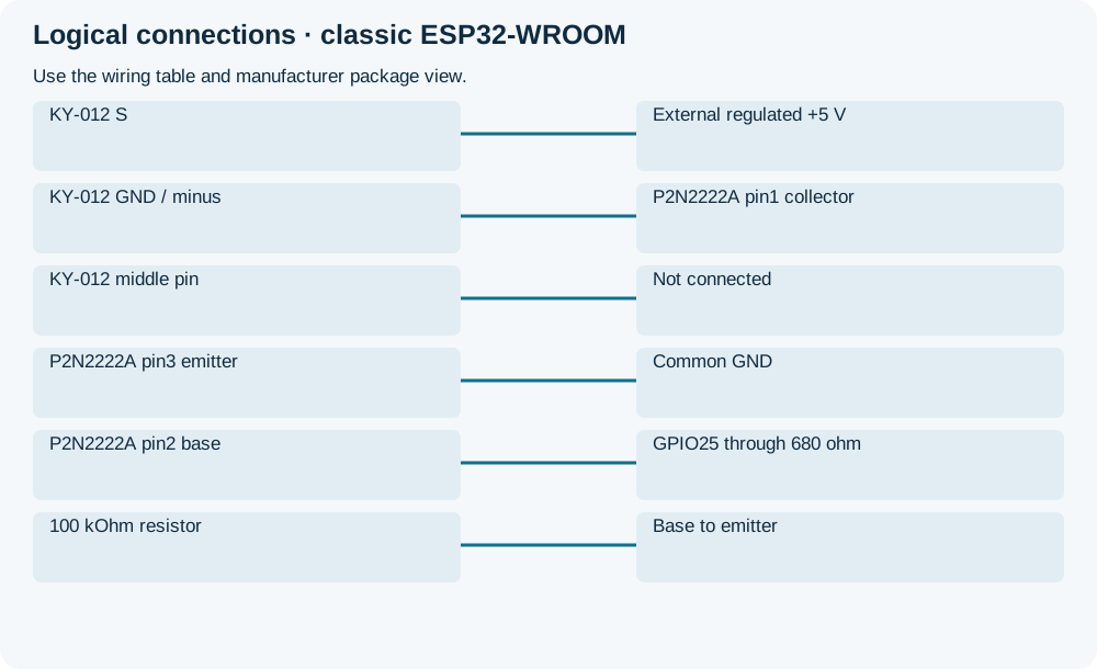
Open wiring diagram at full size (new tab)
-
1
Unplug both supplies. Verify the exact KY-012 wiring and P2N2222A package view; never use artwork as a connector map.
-
2
Join ESP32 GND and external supply negative. Wire the transistor and resistors; keep the switched buzzer return separate from common ground.
-
3
Upload, apply regulated buzzer power and listen briefly; test away from ears.
Wiring and matching Arduino code
Short beep envelope
External +5 V → KY-012 S; KY-012 minus → NPN collector; emitter → common GND. GPIO25 → 680 ohm → base, 100 kOhm base-emitter; middle NC.
active_buzzer_module.ino
#include <Arduino.h>
constexpr uint8_t OUTPUT_PIN = 25;
bool active = false;
uint32_t changedAt = 0;
void setup() {
  Serial.begin(115200);
  pinMode(OUTPUT_PIN, OUTPUT);
  digitalWrite(OUTPUT_PIN, LOW);
  Serial.println("Starts OFF; repeating on/off demonstration");
}
void loop() {
  const uint32_t now = millis();
  const uint32_t interval = active ? 200 : 1800;
  if (now - changedAt >= interval) {
    changedAt = now;
    active = !active;
    digitalWrite(OUTPUT_PIN, active ? HIGH : LOW);
    Serial.println(active ? "ON" : "OFF");
  }
}
HIGH switches the transistor on in this circuit. No tone() or PWM is needed for the active reference. The software OFF state and hardware pull-down assume correct wiring; this is not a fail-safe alarm.
Expected Output
A short repeating beep is expected from the supported reference. A click without a steady tone during the ON interval can indicate a passive device, wrong voltage or poor wiring; do not compensate by blindly changing pin polarity.
How it works
GPIO current enters the base through 680 ohm. The collector switches the buzzer return while its S terminal remains at 5 V. The roughly 3.7 mA base-drive estimate provides margin for the documented 30 mA load using an approximately 10:1 forced-gain design target. Actual junction drop and current vary; no values were measured.
Troubleshooting
| Problem | Possible cause | Solution |
|---|---|---|
| Only clicks | Passive buzzer or unsuitable supply. | Match the exact active reference and check voltage across its S/minus terminals during ON. |
| Continuous sound | Buzzer return bypasses transistor or transistor is shorted. | Unplug power; trace the switched return and verify the base pull-down. |
| A different module behaves backwards | Different trigger circuit or pin order. | Stop and obtain its schematic; neither polarity nor GPIO compatibility follows from the module name. |
Where you use it
- Non-safety-critical reminders
- Button confirmation beeps
- Status alerts with a fixed tone
Continue learning
FAQ
That exact model is not established. The worked reference and diagram are explicitly separate from the family illustration.
An active buzzer is unsuitable for changing musical pitch. That project uses a passive buzzer; follow its separate driver guidance.
Technical references
- Joy-IT KY-012 manual, May 2024 — Powered S terminal, GND, middle NC and wiring.
- Joy-IT active buzzer sensor reference — Active operation and stated maximum current; reference product only.
- onsemi P2N2222A — Transistor lead numbering and saturation guidance.
- Arduino-ESP32 3.3.2 — GPIO/timing review baseline.
- Arduino-ESP32 3.3.2 GPIO implementation — Initialize the GPIO bus with pinMode before digitalWrite; hardware pull-down provides reset bias.