
Before you start
- Board and software
- Low-voltage bench setup as specified below. ESP32 is optional for passive exercises. Coded examples require classic ESP32-WROOM-32/32E DevKit, unused exposed pins, Arduino IDE 2.x and Arduino-ESP32 3.3.2 (review baseline, not a latest-release claim). Other families need their own pin map.
- Supported hardware
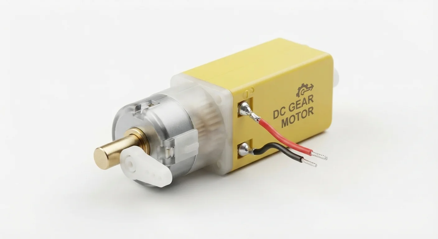
- Approved yellow brushed-DC gearbox illustration, model/voltage/ratio unknown. Worked reference: Adafruit TT motor3777 rated3–6 V; these ratings do not identify the pictured motor.
- Prerequisites and parts
- Documented reference motor, current-limited regulated3 V bench supply, appropriate insulated motor wiring and secure unloaded mount. No ESP32 or ordinary breadboard motor-power path in this first test.
- Libraries
- No firmware or library required for this exercise. Arduino-ESP32 3.3.2 is the site review baseline, not a dependency of this passive setup.
- Expected result
- A documented unloaded motor rotates briefly from its rated external supply; reversing polarity with power off reverses direction. No RPM/torque measurement claimed.
- Verification status
- Documentation and source review only. Not compiled or tested on hardware. The approved product-style illustration identifies a family, not a verified physical pin layout or manufacturer-authenticated board. Follow the logical diagram and documentation for your actual part.
Overview
A brushed DC motor turns electrical power into rotation; gears trade speed for torque. Two terminals do not prove supply voltage, gear ratio or available torque. The approved picture is a family illustration, not a motor specification.
Use the actual datasheet. The worked TT reference is specified for3–6 V. Startup and stall current can far exceed no-load current, so a supply and future driver must be sized for the real motor. Do not hold the shaft stalled to test it.
Technical Specifications
Arduino library: No firmware or library required for this exercise
| Specification | Value | Why it matters |
|---|---|---|
| Reference supply | 3–6 V for Adafruit3777 only | Not a rating inferred for artwork. |
| Direction | Supply polarity | Reverse only with power removed. |
| Feedback | None assumed | Rotation is not measured position/speed. |
Pinout
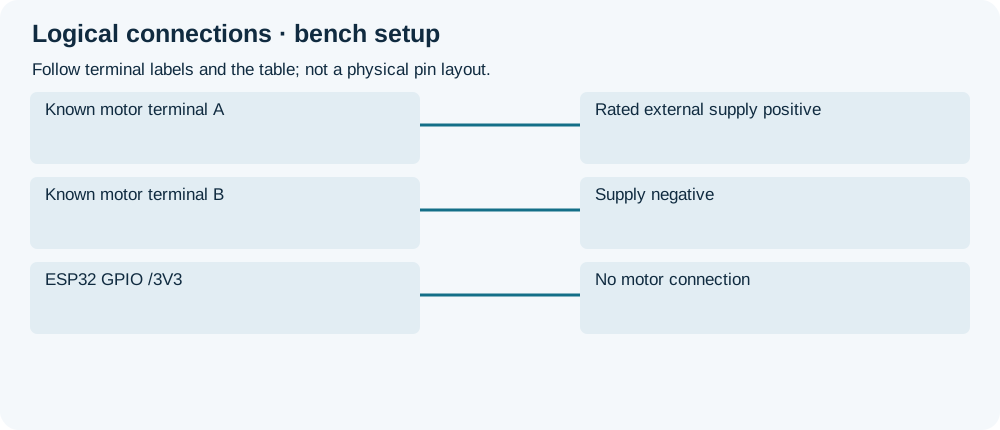
- Known motor terminal A Connection Rated external supply positive Reference test3 V; actual model known.
- Known motor terminal B Connection Supply negative Reverse only unpowered.
- ESP32 GPIO /3V3 Connection No motor connection Driver needed for control.
Wiring Diagram
A documented unloaded motor connects to rated external DC supply; no ESP32 power or signal connection.
| Component terminal | ESP32 / circuit connection | Purpose and qualification |
|---|---|---|
| Known motor terminal A | Rated external supply positive | Reference test3 V; actual model known. |
| Known motor terminal B | Supply negative | Reverse only unpowered. |
| ESP32 GPIO /3V3 | No motor connection | Driver needed for control. |
Open wiring diagram at full size (new tab)
-
1
Verify model/rating, secure motor and keep shaft unloaded.
-
2
With power off connect external rated supply and appropriate wiring.
-
3
Apply briefly, stop, then disconnect before reversing terminals.
Expected Output
Brief rated-power test should rotate the unloaded shaft. A supply hitting its current limit may prevent startup; inspect ratings and mechanics before changing limits. Rotation alone does not establish load capability.
How it works
For controlled speed/direction, choose an H-bridge for actual startup/stall current and low-voltage operation. The existing L298N page explains voltage drop; it is not automatically suitable for a3 V motor. No firmware is useful until a specific compatible driver circuit is selected.
For a future non-isolated driver circuit, join ESP32 signal ground to driver/supply ground while routing motor current directly through the rated driver and supply wiring. The chosen H-bridge must provide documented recirculation/protection paths for inductive current. A single-direction transistor circuit needs its own flyback protection; neither arrangement permits motor power from GPIO.
Troubleshooting
| Problem | Possible cause | Solution |
|---|---|---|
| No rotation | Supply absent/current-limited or shaft obstructed. | Disconnect, inspect and verify actual ratings; do not raise voltage blindly. |
| Hot motor or gearbox noise | Stall/load, excessive voltage or mechanical fault. | Remove power and review motor/mechanical limits. |
| ESP32 resets during later control | Load power routed through board or poor returns. | Use appropriate external motor supply and complete driver protection/wiring. |
Where you use it
- First unloaded drivetrain check
- Selecting a documented driver from actual motor requirements
FAQ
Do not use the DevKit3V3 rail or GPIO as motor supply.
No. Identify the actual product documentation.
Technical references
- Adafruit TT motor3777 — Specific3–6 V reference and load/current qualifications; not artwork authentication.