
Before you start
- Board and software
- Classic ESP32-WROOM-32/32E DevKit with the listed GPIOs exposed and unused. Arduino IDE 2.x; esp32 by Espressif Systems 3.3.2 (review baseline, not a latest-release claim). Select the documented board or ESP32 Dev Module for a generic WROOM board. Other families need their own pin map. Serial Monitor: 115200 baud.
- Supported hardware
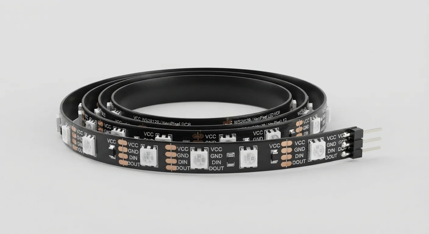
- One physical WS2812B RGB pixel cut at a permitted strip cut mark, with documented 5 V supply, 800 kbit/s data and GRB order. TI SN74AHCT125N DIP-14 buffer. The approved coil illustration does not establish strip revision, density, current, waterproofing or connector order. RGBW and clocked strips need different settings/hardware.
- Prerequisites and parts
- Complete Blink. One correctly identified physical pixel, regulated 5 V supply rated for that pixel’s documented maximum current plus margin, buffer, 100 nF bypass, 10 kOhm input pull-down, 330 ohm data resistor and 1000 microfarad electrolytic rated at least 6.3 V. Power ESP32 by USB; common ground only between supplies.
- Libraries
- Install Adafruit NeoPixel 1.12.3 by Adafruit. Its pinned ESP32 IDF5 branch uses the core 3.x RMT API; reviewed against Arduino-ESP32 3.3.2.
- Expected result
- The single pixel cycles dim red, green and blue, one second each; Serial identifies the commanded color.
- Verification status
- Documentation and source review only. Not compiled or tested on hardware. The approved product-style illustration identifies a family, not a verified physical pin layout or manufacturer-authenticated board. Follow the logical diagram and documentation for your actual part.
Overview
Each addressable pixel receives color bytes and forwards the remaining stream to the next pixel. Data travels from DIN toward DOUT; a connector that looks right can still be at the wrong end. A WS2812B strip is not the same as a four-lead RGB LED whose channels you drive individually.
Begin with one physical pixel so unused downstream pixels cannot retain unknown colors. Do not leave an entire unconfigured coil attached to a supply selected for one LED. Extend only after checking strip specifications, connectors, wire ratings and voltage drop.
Technical Specifications
Arduino library: Adafruit NeoPixel 1.12.3
| Specification | Value | Why it matters |
|---|---|---|
| Reference format | RGB / GRB byte order / 800 kbit/s | Confirm the purchased strip; not RGBW, APA102 or 12 V strips. |
| PIXEL_COUNT | 1 physical pixel in this first test | Changing the constant does not resize the power supply. |
| Current planning | Use the actual strip datasheet maximum | Traditional 60 mA per full-white pixel is a conservative planning rule for some parts, not a universal measured WS2812B rating. |
Pinout
- 74AHCT125 pin14 VCC Supply External regulated +5 V Use SN74AHCT125N DIP-14; not an HC125.
- 74AHCT125 pin7 GND Return Common GND ESP32 GND and external supply negative.
- 74AHCT125 pin2 1A Input GPIO25 + 10 kOhm to GND Pull-down holds input LOW during reset.
- 74AHCT125 pin1 /1OE Enable GND Active LOW; channel1 enabled.
- Unused /OE: 4,10,13 Disable +5 V Outputs6,8,11 left unconnected.
- Unused A: 5,9,12 Input GND Do not leave CMOS inputs floating.
- 100 nF ceramic Bypass Between pins14 and7 Close to buffer; no polarity.
- 74AHCT125 pin3 1Y Data 330 ohm → pixel DIN Resistor close to first pixel; follow data arrow.
- Pixel +5 V Supply External regulated +5 V No connection to ESP32 3.3 V.
- Pixel GND Return Common GND Connect ground first; no hot plugging.
- Pixel DOUT Next pixel Not connected One-pixel reference only.
- 1000 microfarad capacitor Bulk bypass + to +5 V; - to GND Rated ≥6.3 V; verify polarity before power.
Wiring Diagram
GPIO25 → AHCT input; output → 330 ohm → DIN. Pixel/buffer use external5 V and common GND; DOUT unused. Capacitor and buffer terminations as listed.
| Component terminal | ESP32 / circuit connection | Purpose and qualification |
|---|---|---|
| 74AHCT125 pin14 VCC | External regulated +5 V | Use SN74AHCT125N DIP-14; not an HC125. |
| 74AHCT125 pin7 GND | Common GND | ESP32 GND and external supply negative. |
| 74AHCT125 pin2 1A | GPIO25 + 10 kOhm to GND | Pull-down holds input LOW during reset. |
| 74AHCT125 pin1 /1OE | GND | Active LOW; channel1 enabled. |
| Unused /OE: 4,10,13 | +5 V | Outputs6,8,11 left unconnected. |
| Unused A: 5,9,12 | GND | Do not leave CMOS inputs floating. |
| 100 nF ceramic | Between pins14 and7 | Close to buffer; no polarity. |
| 74AHCT125 pin3 1Y | 330 ohm → pixel DIN | Resistor close to first pixel; follow data arrow. |
| Pixel +5 V | External regulated +5 V | No connection to ESP32 3.3 V. |
| Pixel GND | Common GND | Connect ground first; no hot plugging. |
| Pixel DOUT | Not connected | One-pixel reference only. |
| 1000 microfarad capacitor | + to +5 V; - to GND | Rated ≥6.3 V; verify polarity before power. |
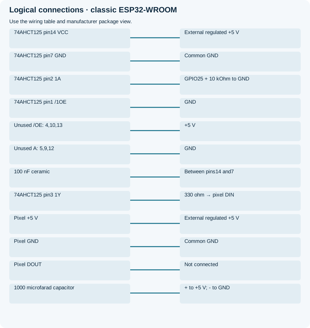
Open wiring diagram at full size (new tab)
-
1
Disconnect both supplies. Identify DIN from arrows/labels and use one physical documented pixel.
-
2
Fit the buffer, pull-down, bypass and polarized capacitor. Check supply polarity; do not tie external +5 V to the USB-powered ESP32.
-
3
Install Adafruit NeoPixel 1.12.3; upload and open Serial at 115200. Apply regulated pixel power only after checking connections.
Wiring and matching Arduino code
Dim red, green and blue test
GPIO25 → AHCT input; output → 330 ohm → DIN. Pixel/buffer use external5 V and common GND; DOUT unused. Capacitor and buffer terminations as listed.
ws2812b_rgb_led_strip.ino
#include <Arduino.h>
#include <Adafruit_NeoPixel.h>
constexpr uint8_t DATA_PIN = 25;
constexpr uint16_t PIXEL_COUNT = 1;
Adafruit_NeoPixel pixels(PIXEL_COUNT, DATA_PIN, NEO_GRB + NEO_KHZ800);
uint8_t phase = 0;
uint32_t changedAt = 0;
bool ready = false;
void setPhase() {
  pixels.clear();
  const uint8_t r = phase == 0 ? 16 : 0;
  const uint8_t g = phase == 1 ? 16 : 0;
  const uint8_t b = phase == 2 ? 16 : 0;
  pixels.setPixelColor(0, pixels.Color(r, g, b));
  pixels.show();
  Serial.println(phase == 0 ? "RED" : (phase == 1 ? "GREEN" : "BLUE"));
}
void setup() {
  Serial.begin(115200);
  pixels.begin();
  if (pixels.getPixels() == nullptr) {
    Serial.println("Pixel buffer allocation failed");
    return;
  }
  pixels.clear();
  pixels.show();
  ready = true;
  setPhase();
  changedAt = millis();
}
void loop() {
  if (!ready) return;
  const uint32_t now = millis();
  if (now - changedAt >= 1000) {
    changedAt = now;
    phase = (phase + 1) % 3;
    setPhase();
  }
}
Low color values reduce demonstration brightness; they are not an electrical current limiter. begin() is void in 1.12.3. getPixels checks allocation only; show() does not acknowledge physical pixel receipt. Test alone before combining other RMT consumers.
Expected Output
The physical pixel should cycle red, green and blue. Wrong colors suggest byte-order mismatch, not necessarily bad wiring. Printed color names only show what software sent; the one-wire interface supplies no readback.
How it works
The pinned library serializes color bytes using ESP32 RMT rather than LEDC PWM. The buffer raises the data level; supply and signal voltage are separate requirements. Modern WS2812B revisions vary, so do not infer an input threshold or per-pixel current from the family name. Extra pixels increase full-load current and may need distributed power injection; low software brightness does not remove the need for suitable wiring and supply protection.
Troubleshooting
| Problem | Possible cause | Solution |
|---|---|---|
| Pixel remains dark | Wrong DIN end, missing ground, buffer disabled or supply absent. | Power off and trace the arrow, 5 V rail and /1OE before changing code. |
| Colors are swapped | Different color byte order. | Confirm strip specifications; choose the appropriate NEO_RGB/NEO_GRB order, not arbitrary GPIO changes. |
| Random colors or ESP32 resets | Poor signal integrity, supply drop or shared power wiring. | Check the resistor/buffer/common ground and actual supply budget. Do not connect a long coil to this one-pixel circuit. |
| Library or RMT errors | Wrong core/library version or peripheral resource conflict. | Verify the pinned pair and run this sketch alone; no successful compilation is claimed here. |
Where you use it
- One-pixel status indicator
- Addressable color lessons
- Preparation for a music visualizer with separate input and power requirements
Continue learning
Related projects
FAQ
No. Revisions and products vary. Design from the actual datasheet and worst-case count; the illustration cannot establish current.
This example deliberately uses AHCT buffering rather than assuming an unspecified revision accepts 3.3 V data.
Technical references
- Worldsemi WS2812 family — Family and revision differences; verify the purchased strip documentation.
- Adafruit NeoPixel best practices — Buffering, resistor, capacitor and safe power connections.
- Adafruit NeoPixel 1.12.3 — Pinned constructor, color and output APIs.
- NeoPixel 1.12.3 ESP32 implementation — IDF5/core3.x RMT branch reviewed.
- TI SN74AHCT125 — TTL-compatible 5 V buffer and package view.
- Arduino-ESP32 3.3.2 RMT API — Pinned rmtInit/rmtWrite interfaces; source review only.