
Before you start
- Board and software
- Classic ESP32-WROOM-32/32E DevKit with these GPIOs exposed and unused. Arduino IDE 2.x; esp32 by Espressif Systems 3.x (API review baseline 3.3.2, not a latest-version claim). Select the exact board or ESP32 Dev Module for a generic WROOM board. Other ESP32 families need their own pin map. Serial Monitor: 115200 baud.
- Hardware assumption
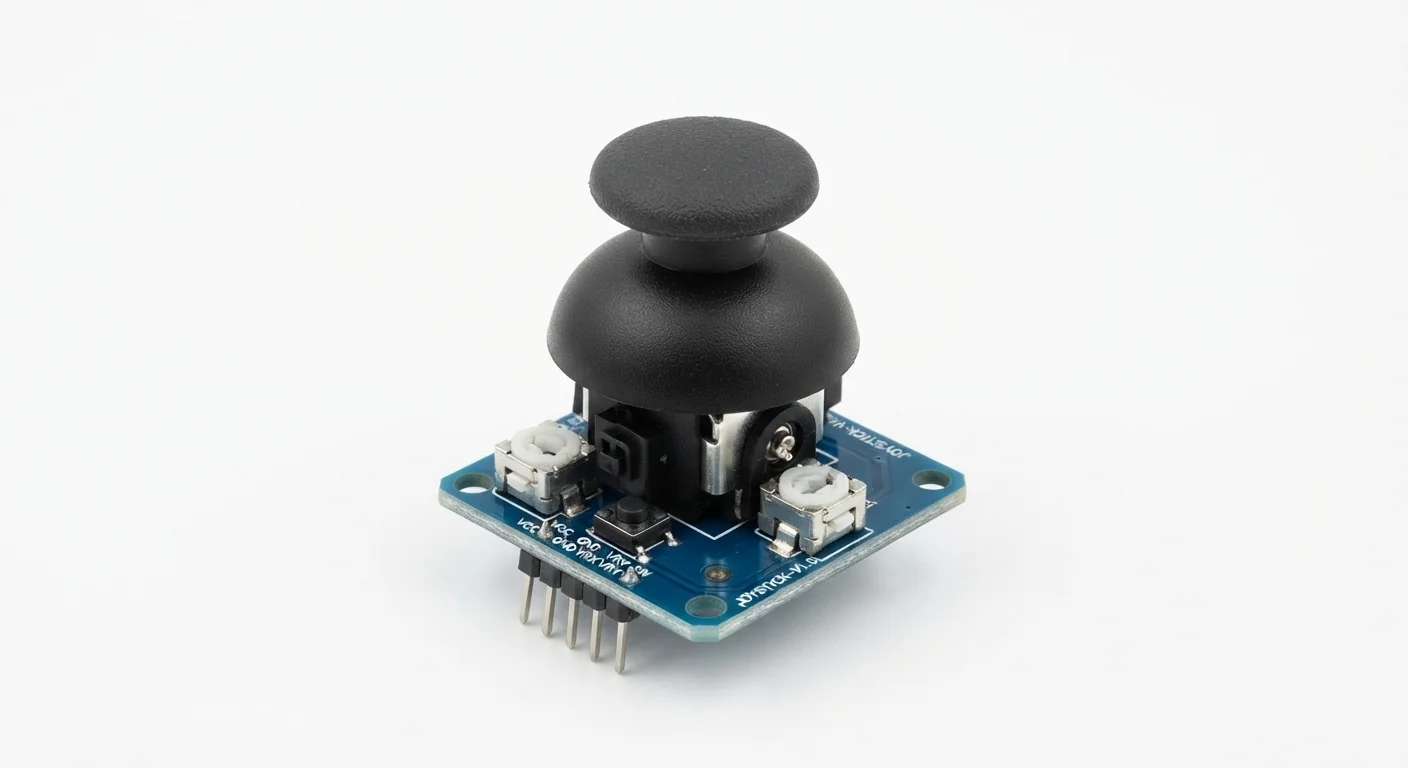
- A passive two-potentiometer joystick breakout with VRx, VRy and a normally open SW contact to GND, documented to operate at 3.3 V. No model, resistance or physical header order is inferred. This is not an I2C/Qwiic joystick.
- Prerequisites and parts
- First complete Arduino IDE setup and Blink. Joystick, breadboard and wires; verify the breakout has no 5 V-only electronics or pull-ups.
- Expected result
- X and Y readings change as the stick moves; SW reads LOW when pressed. Center and end readings vary, so calibrate your own module.
- Verification status
- Reviewed against the technical references below. Not compiled for an ESP32 or tested on hardware in this update. The approved product-style illustration identifies the family; follow documented terminal labels and the logical wiring diagram, not its rendered pin positions.
Overview
Each axis is a potentiometer whose wiper voltage changes with movement. The ESP32 samples those voltages; a separate switch detects a press on the stick.
Power the assumed passive module from 3.3 V, not 5 V: otherwise its wipers can drive unsafe voltage into ESP32 inputs. Read GPIO32 and GPIO33, which are ADC1 on classic ESP32. The illustration does not verify the circuit inside another module.
Technical Specifications
Arduino library: No additional library; Arduino-ESP32 ADC and GPIO APIs
| Specification | Value | Why it matters |
|---|---|---|
| Interface | Two analog wipers + one switch | Verify VRx/VRy/SW labels; physical pin order varies. |
| Supply | 3.3 V in this build | Assumes passive potentiometers and a switch, not an active 5 V module. |
| Axes | GPIO32 and GPIO33 (ADC1) | Avoid the classic ESP32 ADC2/Wi-Fi conflict; other families differ. |
| Resolution | 12-bit raw counts, 0–4095 | Counts are not calibrated volts or guaranteed full mechanical range. |
| Attenuation | ADC_11db | Classic ESP32 documented measurable range is about 150–3100 mV; endpoints may clip even with safe 3.3 V supply. |
Pinout
- VCC / + Potentiometer supply ESP32 3.3 V Only for a module documented for this passive 3.3 V use.
- GND / - Reference ESP32 GND Shared reference for both axes and switch.
- VRx / X X wiper GPIO32 ADC1 input; never a 5 V wiper.
- VRy / Y Y wiper GPIO33 ADC1 input; orientation may reverse an axis.
- SW Push switch GPIO27 with INPUT_PULLUP Assumes switch closes to GND. GPIO34–39 lack internal pull resistors on classic ESP32.
Wiring Diagram
VCC to 3.3 V, GND to GND, VRx to GPIO32, VRy to GPIO33 and SW to GPIO27. This example prints raw axis readings and the instantaneous switch level.
| Component terminal | ESP32 / circuit connection | Purpose and qualification |
|---|---|---|
| VCC / + | ESP32 3.3 V | Only for a module documented for this passive 3.3 V use. |
| GND / - | ESP32 GND | Shared reference for both axes and switch. |
| VRx / X | GPIO32 | ADC1 input; never a 5 V wiper. |
| VRy / Y | GPIO33 | ADC1 input; orientation may reverse an axis. |
| SW | GPIO27 with INPUT_PULLUP | Assumes switch closes to GND. GPIO34–39 lack internal pull resistors on classic ESP32. |
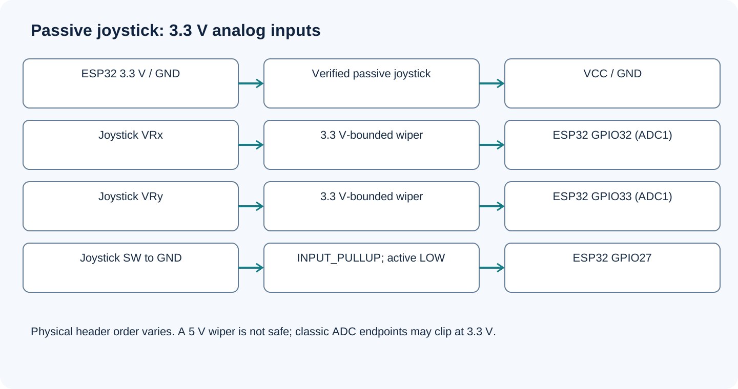
Open wiring diagram at full size (new tab)
-
1
With power disconnected, verify the module circuit/labels and its 3.3 V suitability.
-
2
Connect only the five named signals, then select the classic WROOM board profile.
-
3
Upload and open Serial Monitor; move each axis separately and press the stick.
-
4
Observe the actual center and extremes before choosing a dead zone or mapping values to motion.
Wiring and matching Arduino code
Raw axis and push-switch readout
VCC to 3.3 V, GND to GND, VRx to GPIO32, VRy to GPIO33 and SW to GPIO27. This example prints raw axis readings and the instantaneous switch level.
analog_joystick_esp32.ino
#include <Arduino.h>
constexpr uint8_t X_PIN = 32, Y_PIN = 33, SW_PIN = 27;
void setup() {
  Serial.begin(115200);
  pinMode(SW_PIN, INPUT_PULLUP);
  analogReadResolution(12);
  analogSetPinAttenuation(X_PIN, ADC_11db);
  analogSetPinAttenuation(Y_PIN, ADC_11db);
}
void loop() {
  int x = analogRead(X_PIN);
  int y = analogRead(Y_PIN);
  Serial.printf("X=%d Y=%d SW=%s\n", x, y,
                digitalRead(SW_PIN) == LOW ? "pressed" : "released");
  delay(100);
}
Raw values demonstrate input changes, not calibrated voltage. Center need not be 2048, and 3.3 V can clip the classic ESP32 ADC measurement range. This monitor does not debounce SW; use the linked debouncing lesson before counting presses.
Expected Output
At 115200 baud, X and Y should vary with the stick and SW should change between released and pressed. Numbers shown on your board depend on its potentiometers and ADC behavior. Establish a dead zone from observed center noise; do not assume an exact center or endpoint value.
How it works
A potentiometer is a divider, so the wiper follows its position between the supply rails. A higher axis supply can create a higher output: analog input is not automatically voltage-safe. For control projects, calibrate each axis, allow a center dead zone and debounce the switch separately.
Troubleshooting
| Problem | Possible cause | Solution |
|---|---|---|
| Axis remains near an endpoint | Wrong pin, loose wiper wire or clipped ADC range. | Check GPIO numbers, 3.3 V supply and both axis labels. Test each axis alone; clipping is not automatically a broken potentiometer. |
| Center jitters | Potentiometer/ADC noise and mechanical variation. | Use short wires, stable supply, averaging and a measured dead zone; do not demand exactly 2048. |
| Axes fail with Wi-Fi | ADC2 used on classic ESP32 or wrong family map. | Use the named ADC1 GPIO32/33 here and verify your board family. |
| SW always pressed | Wrong terminal, a short or mismatched switch circuit. | Check that SW is normally open to GND and GPIO27 has INPUT_PULLUP; inspect module pull-ups. |
Where you use it
- Menu navigation
- Joystick-controlled robot arm
- Two-axis position input
Continue learning
Related projects
FAQ
Not with direct axis connections in this example. The passive wipers may then reach 5 V. Use the assumed 3.3 V-compatible module or a properly documented interface.
Mechanical center, potentiometer tolerance and ADC response vary. Calibrate instead of assuming ideal midpoint counts.
No. The linked project uses its own ADC and servo pins. Follow one complete matching wiring/code set.
Technical references
- SparkFun Thumb Joystick hookup guide — Two potentiometers and push switch; module example, not proof of the pictured board.
- Espressif ADC API — Resolution, per-pin attenuation and classic ESP32 measurable range.
- Espressif GPIO API — INPUT_PULLUP and digitalRead.
- Espressif ESP32 ADC limitations — Classic ESP32 ADC2/Wi-Fi sharing restrictions.
Downloads
Official manufacturer PDF for teachers and advanced builders.
No separate datasheet is needed for this beginner guide.