
Before you start
- Board and software
- Classic ESP32-WROOM-32/32E DevKit with the specified unused GPIOs exposed; Arduino IDE 2.x and Arduino-ESP32 3.x. Other families require their own pin map. Serial Monitor: 115200 baud. No extra library.
- Supported hardware
- One documented low-current red indicator LED suitable for a 3.3 V resistor-limited GPIO circuit. Kingbright WP7113ID is a datasheet example, not identification of the illustrated assortment. Excludes high-power LEDs, built-in-resistor lamps and addressable LEDs.
- Prerequisites and parts
- Complete IDE setup and Blink first. Red LED, known 470 ohm / 0.25 W resistor, breadboard and wires. Confirm the LED datasheet and polarity.
- Expected result
- Red LED alternates one second on and one second off; Serial reports ON and OFF. Brightness is part-dependent.
- Verification limits
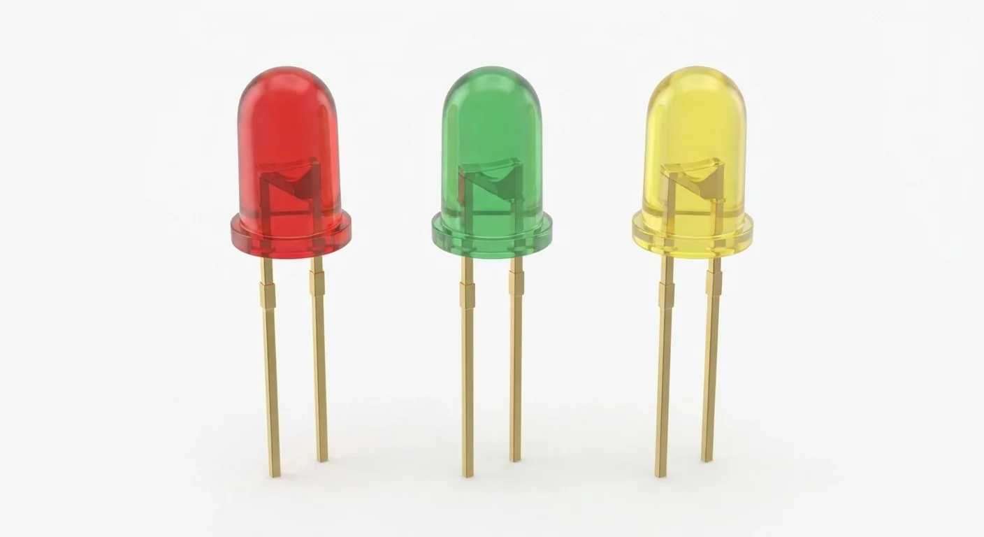
- Documentation and automated content/browser checks only in this update. No ESP32 compilation or physical hardware testing. The approved image depicts a component family; it does not authenticate a model, rating or terminal order.
Overview
An LED conducts mainly in one direction and converts some electrical energy into light. A series resistor limits current. Lens color alone does not establish emitted color, forward voltage, current rating or package size.
Use the actual datasheet or a power-off diode test to identify anode and cathode. A longer lead or flat case edge can be a clue, but cut leads and unusual packages make those clues unreliable. The illustration is not a polarity diagram.
Technical Specifications
Arduino library: Arduino-ESP32 3.x; no additional library
| Specification | Value | Why it matters |
|---|---|---|
| Example resistor | 470 ohm, 0.25 W | At 3.3 V the resistor limits even a shorted LED to about 7 mA; actual LED current is lower. |
| Polarity | Anode toward GPIO; cathode to GND | Identify from the actual datasheet or diode test. |
| Illustrated colors | Red / green / yellow lenses | No exact part ratings or dimensions inferred. |
| Supply in this example | GPIO25 supplies the example through 470 ohms; no 5 V connection. | Applies only to the supported hardware assumptions above. |
| ESP32 signal compatibility | 3.3 V GPIO output; HIGH lights the correctly oriented LED. | Applies only to the supported hardware assumptions above. |
| Required protection | One series resistor per LED; choose from actual forward-voltage/current limits. Never connect an LED directly across a GPIO and ground. | Applies only to the supported hardware assumptions above. |
Pinout
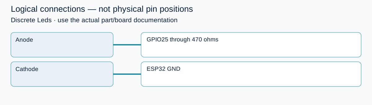
- Anode Identify the real anode; resistor can be on either side of a single series circuit. GPIO25 through 470 ohms Identify the real anode; resistor can be on either side of a single series circuit.
- Cathode Do not infer lead identity from artwork. ESP32 GND Do not infer lead identity from artwork.
Wiring Diagram
GPIO25 → 470 ohm resistor → LED anode; LED cathode → GND.
| Identified terminal | Connection | Qualification |
|---|---|---|
| Anode | GPIO25 through 470 ohms | Identify the real anode; resistor can be on either side of a single series circuit. |
| Cathode | ESP32 GND | Do not infer lead identity from artwork. |
Open wiring diagram at full size (new tab)
-
1
Unplug USB before wiring; identify polarity using documentation or a diode test.
-
2
Build the series circuit; confirm breadboard rows do not bypass the resistor.
-
3
Upload and open Serial Monitor at 115200 baud.
Wiring and matching Arduino code
External red LED blink
GPIO25 → 470 ohm resistor → LED anode; LED cathode → GND.
discrete_leds_esp32.ino
#include <Arduino.h>
constexpr uint8_t LED_PIN = 25;
void setup() {
  pinMode(LED_PIN, OUTPUT);
  digitalWrite(LED_PIN, LOW);
  Serial.begin(115200);
}
void loop() {
  digitalWrite(LED_PIN, HIGH);
  Serial.println("ON");
  delay(1000);
  digitalWrite(LED_PIN, LOW);
  Serial.println("OFF");
  delay(1000);
}
This GPIO differs from some linked tutorials; follow this page's wiring. No onboard LED assumed.
Expected Output
Red LED alternates one second on and one second off; Serial reports ON and OFF. Brightness is part-dependent.
How it works
HIGH places about 3.3 V across the series path. Estimate current with I=(VGPIO−VF)/R, then check the actual part limits. A red LED at an illustrative 2.0 V forward drop draws roughly 2.8 mA through 470 ohms; this is a calculation, not a measurement. Green or blue parts with higher forward voltage may be dim or fail to light on this rail.
Troubleshooting
| Problem | Possible cause | Solution |
|---|---|---|
| Serial changes but LED stays dark | Reversed LED, wrong row or unsupported forward voltage. | Power off; confirm polarity and series path. Try the documented red indicator LED, not a higher-voltage lamp. |
| LED stays on | Wrong GPIO or wiring to the supply instead of GPIO25. | Trace GPIO25 to the resistor and check the uploaded sketch. |
| LED is unexpectedly bright or hot | Missing/bypassed resistor or unsuitable part. | Disconnect immediately; verify resistance and actual LED limits before retrying. |
Where you use it
- Blink learning exercise
- Low-current status indication
- Button-controlled LED
Continue learning
Related projects
FAQ
Use one resistor for each independently driven LED. A shared resistor makes current and brightness depend on which LEDs are on.
It is a common clue, not a universal guarantee. Use the actual datasheet or a diode test, especially with trimmed leads.
Technical references
- Espressif GPIO API — Pin modes and digital output on Arduino-ESP32.
- Kingbright WP7113ID datasheet — Example red indicator LED; not identification of the artwork.