
Before you start
- Board and software
- Classic ESP32-WROOM-32/32E DevKit with the listed GPIOs exposed and unused. Arduino IDE 2.x; esp32 by Espressif Systems 3.3.2 (review baseline, not a latest-release claim). Select the documented board or ESP32 Dev Module for a generic WROOM board. Other families need their own pin map. Serial Monitor: 115200 baud.
- Supported hardware
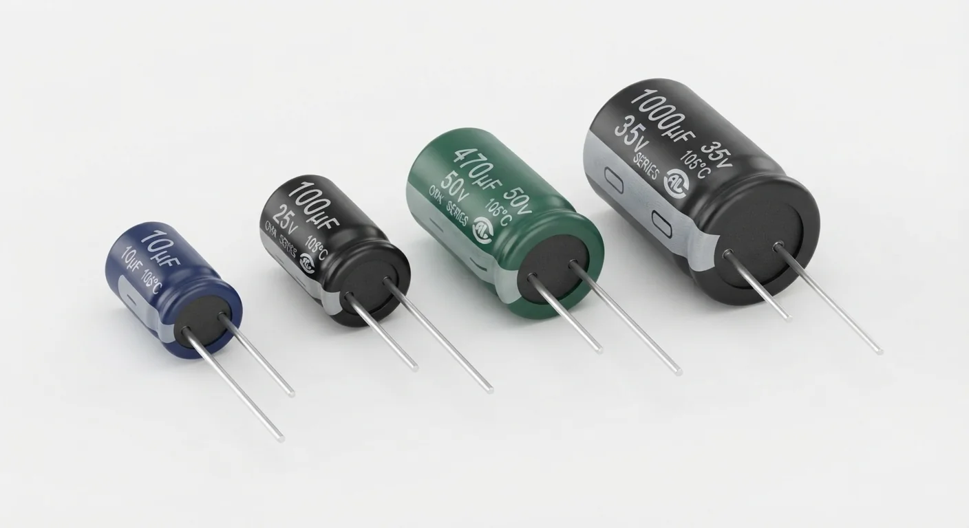
- Known radial aluminum electrolytic, 100 µF rated at least 10 V, documented for the temperature/circuit. The assortment artwork does not authenticate values, series, ESR or lifetime.
- Prerequisites and parts
- Regulated current-limited 5 V supply, known 100 µF / ≥10 V capacitor, 1 kOhm 0.25 W resistor, voltmeter and insulated connections. Read the actual part datasheet; keep this exercise separate from ESP32 GPIO and USB rails.
- Libraries
- No firmware/library required for the meter exercise. Arduino-ESP32 3.3.2 is the site example baseline, not a dependency of this passive part.
- Expected result
- A voltmeter shows charging toward 5 V and discharge toward zero after supply removal. No timing/ripple measurement performed.
- Verification status
- Documentation and source review only. Not compiled or tested on hardware. The approved product-style illustration identifies a family, not a verified physical pin layout or manufacturer-authenticated board. Follow the logical diagram and documentation for your actual part.
Overview
A capacitor stores charge and supports brief current changes near a load. Capacitance is given in microfarads (µF); the voltage marking is a limit, not a voltage it generates. Polarized aluminum electrolytics require correct polarity.
A minus stripe commonly identifies the negative lead on radial parts. Follow the manufacturer drawing; trimmed lead length is not reliable identification. The picture is a generic assortment, not verified ratings. For an actual supply, also check ripple current, ESR, temperature and lifetime requirements.
Technical Specifications
Arduino library: No software library required for the passive meter exercise.
| Specification | Value | Why it matters |
|---|---|---|
| Worked capacitance | 100 µF | Verify actual part label/datasheet; tolerance applies. |
| Voltage rating | ≥10 V for this 5 V exercise | Example margin, not a universal design rule. |
| Series resistor | 1 kOhm, 0.25 W | Initial current about 5 mA; initial resistor power about 25 mW. |
| Ideal time constant | RC = 0.1 s | Five time constants ≈0.5 s; tolerance/leakage/meter update rate affect observation. |
Pinout
- Supply +5 V Charge 1 kOhm → capacitor + No ESP32 GPIO/USB positive rail connected.
- Capacitor − Return Supply negative / meter − Identify polarity from manufacturer marking.
- Voltmeter + Measure Capacitor + DC voltage mode; meter − at capacitor −.
- After supply removal: 1 kOhm Discharge Across capacitor + and − Disconnect supply first; check near-zero voltage.
Wiring Diagram
Charge: +5 V → 1 kOhm → capacitor +; capacitor − → supply negative. Meter across capacitor. After removing supply, discharge through 1 kOhm.
| Component terminal | ESP32 / circuit connection | Purpose and qualification |
|---|---|---|
| Supply +5 V | 1 kOhm → capacitor + | No ESP32 GPIO/USB positive rail connected. |
| Capacitor − | Supply negative / meter − | Identify polarity from manufacturer marking. |
| Voltmeter + | Capacitor + | DC voltage mode; meter − at capacitor −. |
| After supply removal: 1 kOhm | Across capacitor + and − | Disconnect supply first; check near-zero voltage. |
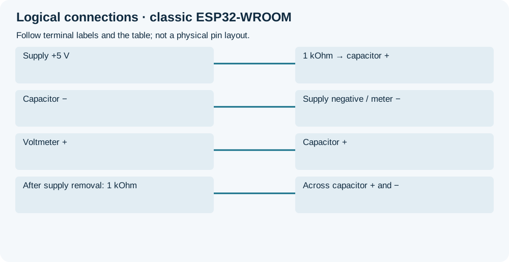
Open wiring diagram at full size (new tab)
-
1
With power off and capacitor discharged, verify polarity/ratings. Wire the charge circuit and meter in DC voltage mode.
-
2
Apply regulated 5 V through 1 kOhm. Settled voltage should approach 5 V; a slow meter may miss the short transient.
-
3
Switch off and disconnect the supply connection. Put the resistor across capacitor leads to discharge. Check voltage before handling and recheck for returning residual charge.
Expected Output
Settled voltage should approach 5 V; discharge should move it toward zero. The ideal 0.1 s time constant is calculated, not measured. Voltage alone cannot establish capacitance, ESR, ripple rating or health.
How it works
Charge current falls as capacitor voltage approaches the supply. Removing the supply and adding a resistor across the terminals gives a controlled discharge path. This is a small low-voltage circuit; high-energy storage needs separate resistor power/energy design.
A real load often needs local bulk capacitance across supply/ground plus specified high-frequency bypassing. The exercise resistor is not a rule for a finished motor/LED supply. A4988 and WS2812B have different required values/placement; follow those complete circuits. Extra capacitance cannot fix an undersized supply, poor ground or unsafe signal voltage.
Troubleshooting
| Problem | Possible cause | Solution |
|---|---|---|
| Warming, swelling or leakage | Reverse polarity or unsuitable/stressed part. | Remove power safely; do not reuse a damaged part. Check actual circuit/ratings. |
| Voltage stays low | Wrong connection, supply absent or leaking/damaged part. | Disconnect/discharge before inspection; a voltmeter cannot diagnose every fault. |
| Transient not visible | Meter slower than charging. | Use settled voltage for connection checking; do not claim timing from a slow display. |
| ESP32 resets despite added capacitance | Supply/wiring/placement issue remains. | Follow load power budgeting; do not add unknown capacitance to regulator outputs without documentation. |
Where you use it
- Learning polarity, units and stored charge
- Choosing documented bulk support for LED/motor supplies
FAQ
No. Capacitance and voltage rating are separate markings.
No blanket substitution; follow the load datasheet for bulk and high-frequency bypassing.
Technical references
- Nichicon application guidelines — Polarity, electrical stress, residual voltage and resistor discharge; not authentication of the assortment.
- Panasonic polarity explanation — Polarized aluminum electrolytics and reverse voltage.