
Before you start
- Board and software
- Classic ESP32-WROOM-32/32E DevKit with the listed GPIOs exposed and unused. Arduino IDE 2.x; esp32 by Espressif Systems 3.3.2 (review baseline, not a latest-release claim). Select the documented board or ESP32 Dev Module for a generic WROOM board. Other families need their own pin map. Serial Monitor: 115200 baud.
- Supported hardware
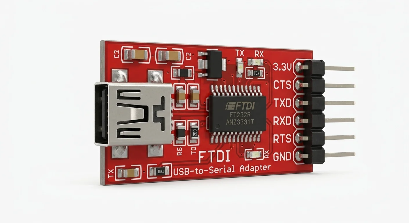
- FT232R-family USB-UART carrier with manufacturer schematic confirming VCCIO at 3.3 V and non-inverted TTL UART TX/RX. Artwork is not an identified board revision; RL suffix, jumper behavior and authenticity are unverified. No RS-232 adapter.
- Prerequisites and parts
- Upload through the DevKit USB first. Two data-capable USB cables, documented 3.3 V adapter, signal/ground wires and terminal program. GPIO16/17 must be available on this WROOM board; other modules may use them for PSRAM.
- Libraries
- Arduino-ESP32 3.3.2 built-in HardwareSerial only. FTDI VCP driver if needed for the actual bridge.
- Expected result
- Short text sent through the adapter terminal is echoed there; the ESP32 USB Serial Monitor also shows each received byte.
- Verification status
- Documentation and source review only. Not compiled or tested on hardware. The approved product-style illustration identifies a family, not a verified physical pin layout or manufacturer-authenticated board. Follow the logical diagram and documentation for your actual part.
Overview
A USB-UART adapter gives a computer a serial port with TX, RX and ground. It is useful when the ESP32 USB port already carries debugging output. It does not turn arbitrary voltage levels into safe inputs.
FT232R separates its main supply from VCCIO, which sets interface levels. A header marked 3.3V may be a power output while TX uses another voltage. Read the actual carrier schematic/configuration; disconnected from ESP32, check idle TX against GND. If its signal level cannot be established, stop before connecting. The illustration cannot establish a jumper position or header order.
Technical Specifications
Arduino library: Arduino-ESP32 3.3.2 built-in HardwareSerial; no extra sketch library.
| Specification | Value | Why it matters |
|---|---|---|
| UART format | 115200 baud, 8N1 | Both terminals: flow control and local echo off. |
| WROOM pins | GPIO16 RX, GPIO17 TX | Explicit Serial2 assignment; separate from board USB/UART0. |
| Adapter signal | Documented 3.3 V VCCIO | Verify the carrier schematic; illustration is not a circuit reference. |
| ESP32 signal protection | 3.3 V UART only; no 5 V signal | Do not connect an unknown-voltage TX output; leave adapter power outputs disconnected. |
Pinout
- Adapter TXD / TXO Output GPIO16 (ESP32 RX) Manufacturer-confirmed 3.3 V UART.
- Adapter RXD / RXI Input GPIO17 (ESP32 TX) Crossed, from adapter perspective.
- Adapter GND Reference ESP32 GND Wire with both USB cables removed.
- VCC / 3V3 / 5V Power Leave disconnected ESP32 has its own USB supply.
- DTR / RTS / CTS Control Leave disconnected Flow control off; no reset wiring.
Wiring Diagram
Adapter TX → GPIO16, RX ← GPIO17, GND ↔ GND. Separate USB power; no positive-rail connection.
| Component terminal | ESP32 / circuit connection | Purpose and qualification |
|---|---|---|
| Adapter TXD / TXO | GPIO16 (ESP32 RX) | Manufacturer-confirmed 3.3 V UART. |
| Adapter RXD / RXI | GPIO17 (ESP32 TX) | Crossed, from adapter perspective. |
| Adapter GND | ESP32 GND | Wire with both USB cables removed. |
| VCC / 3V3 / 5V | Leave disconnected | ESP32 has its own USB supply. |
| DTR / RTS / CTS | Leave disconnected | Flow control off; no reset wiring. |
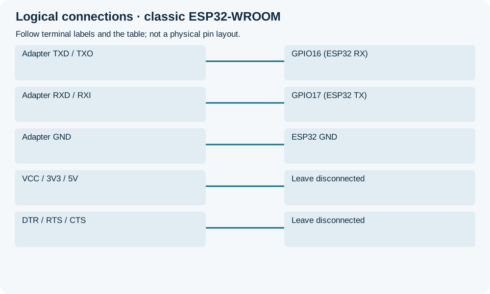
Open wiring diagram at full size (new tab)
-
1
Upload through DevKit USB before attaching the adapter. Confirm voltage configuration and pin availability.
-
2
Unplug both devices, wire only TX/RX/GND and check for shorts. Identify separate OS ports by unplugging one device at a time.
-
3
Open both terminals at 115200 8N1, flow control/local echo off. Send a short line from the adapter terminal.
Wiring and matching Arduino code
Separate UART byte echo
Adapter TX → GPIO16, RX ← GPIO17, GND ↔ GND. Separate USB power; no positive-rail connection.
ft232r_usb_ttl.ino
#include <Arduino.h>
constexpr int8_t UART_RX = 16;
constexpr int8_t UART_TX = 17;
void setup() {
  Serial.begin(115200);
  Serial2.begin(115200, SERIAL_8N1, UART_RX, UART_TX);
  Serial.println("Adapter terminal: 115200 8N1, flow control off");
}
void loop() {
  for (uint8_t n = 0; n < 32 && Serial2.available() > 0; ++n) {
    const int value = Serial2.read();
    if (value >= 0) {
      Serial2.write(static_cast<uint8_t>(value));
      Serial.write(static_cast<uint8_t>(value));
    }
  }
  delay(1);
}
Pinned HardwareSerial begin(baud, config, RX, TX) API. Short-line diagnostic, not a high-rate bridge: long streams can overflow buffers. No automatic boot/reset or voltage measurement.
Expected Output
A short line should echo once in the adapter terminal and appear in DevKit Serial Monitor. Local echo can produce duplicate text even with bad wiring; turn it off before interpreting the result.
How it works
Serial2 receives on GPIO16, echoes on GPIO17 and copies each byte to Serial on the board USB bridge. Enumeration, UART communication and flashing are separate tasks. This tests communication after a normal USB upload, not an adapter-specific boot circuit.
Troubleshooting
| Problem | Possible cause | Solution |
|---|---|---|
| No adapter port | Charge-only cable, missing driver or wrong assumed bridge. | Identify the device; use FTDI drivers only for FTDI hardware and try a data cable. |
| Port opens but no echo | TX/RX not crossed, no ground or wrong pins. | Check the table and available WROOM pins; confirm baud/framing and flow control. |
| Garbled text | Framing mismatch, noise or unsafe signal voltage. | Verify 115200 8N1 and carrier documentation before reconnecting; idle voltage alone is not a schematic. |
| Resets or upload failures | Power/modem-control outputs accidentally connected. | Remove VCC/DTR/RTS wiring; upload through original board USB. |
Where you use it
- A second serial diagnostic console
- Checking a documented adapter before adding a UART peripheral
Continue learning
FAQ
No. Verify VCCIO and the actual carrier circuit.
No. This WROOM example requires unused exposed pins; PSRAM modules and other families need their own map.
Technical references
- FTDI FT232R datasheet — VCC versus VCCIO and UART roles; not identification of the artwork.
- FTDI datasheet version 2.10, manufacturer-authored mirror — Reviewed VCCIO and USB-to-MCU interface; original FTDI host blocked automated retrieval.
- Arduino-ESP32 3.3.2 HardwareSerial — Pinned begin/read/write interfaces.
- FTDI VCP drivers — Driver for the actual USB bridge.