
Before you start
- Board and software
- Low-voltage bench setup as specified below. ESP32 is optional for passive exercises. Coded examples require classic ESP32-WROOM-32/32E DevKit, unused exposed pins, Arduino IDE 2.x and Arduino-ESP32 3.3.2 (review baseline, not a latest-release claim). Other families need their own pin map.
- Supported hardware
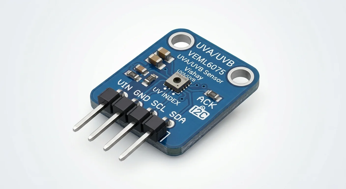
- Approved VEML6075-labelled illustration, exact carrier unverified. Worked reference: Adafruit VEML6075 breakout powered at 3.3 V; use its documented labels, not artwork pin positions.
- Prerequisites and parts
- Classic WROOM DevKit, documented reference breakout and short wires. GPIO21 SDA / GPIO22 SCL exposed and unused. I2C scanner can check response, not prove identity.
- Libraries
- Adafruit VEML6075 Library 2.2.2 and its Adafruit BusIO dependency; Arduino-ESP32 3.3.2 Wire. Install dependencies through Library Manager.
- Expected result
- Serial prints compensated UVA/UVB counts and estimated UV index; initialization failure is reported instead of invented readings.
- Verification status
- Documentation and source review only. Not compiled or tested on hardware. The approved product-style illustration identifies a family, not a verified physical pin layout or manufacturer-authenticated board. Follow the logical diagram and documentation for your actual part.
Overview
VEML6075 measures two ultraviolet bands and compensation channels. The library converts them to compensated UVA/UVB counts and an estimated UV index using coefficients. Counts are not watts per square meter; the estimate depends on optical conditions and calibration.
The approved marking supports the sensor family, not a verified carrier circuit. The bare sensor and breakout have different supply provisions. This example uses the documented Adafruit board at 3.3 V so bus pull-ups are compatible with ESP32. Do not expose yourself to UV lamps to test it; indoor/window-filtered light may give small or negative compensated values.
This is legacy hardware: the reference breakout is listed as no longer stocked. The instructions are for an existing documented board, not a claim of current availability.
Technical Specifications
Arduino library: Adafruit VEML6075 2.2.2; Adafruit BusIO dependency
| Specification | Value | Why it matters |
|---|---|---|
| Address | 0x10 | Fixed VEML6075 address; response alone is not identity. |
| Library output | Compensated counts and estimated UVI | Not calibrated irradiance or a health dosimeter. |
| Bus | GPIO21 SDA, GPIO22 SCL at 100 kHz | Classic WROOM reference pins only. |
Pinout
- VIN Supply ESP32 3V3 Documented reference only.
- GND Reference ESP32 GND Common ground.
- SDA Data GPIO21 3.3 V pull-up domain.
- SCL Clock GPIO22 3.3 V pull-up domain.
- 3v3 Output Leave disconnected Reference regulator output.
Wiring Diagram
Adafruit reference VIN3.3 V/GND, SDA21/SCL22; 3v3 unconnected.
| Component terminal | ESP32 / circuit connection | Purpose and qualification |
|---|---|---|
| VIN | ESP32 3V3 | Documented reference only. |
| GND | ESP32 GND | Common ground. |
| SDA | GPIO21 | 3.3 V pull-up domain. |
| SCL | GPIO22 | 3.3 V pull-up domain. |
| 3v3 | Leave disconnected | Reference regulator output. |
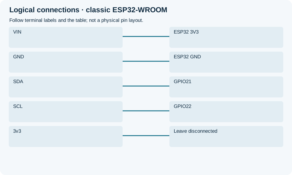
Open wiring diagram at full size (new tab)
-
1
Verify actual board schematic and sensor marking with all power removed.
-
2
Wire labelled terminals; run scanner if initialization fails.
-
3
Upload and read Serial at 115200 baud; no artificial UV source required.
Wiring and matching Arduino code
Read UV channels with initialization checks
Adafruit reference VIN3.3 V/GND, SDA21/SCL22; 3v3 unconnected.
veml6075_uv_sensor.ino
#include <Arduino.h>
#include <Wire.h>
#include <Adafruit_VEML6075.h>
#include <math.h>
Adafruit_VEML6075 uv;
bool ready = false;
void setup() {
  Serial.begin(115200);
  Wire.begin(21, 22, 100000);
  ready = uv.begin(VEML6075_100MS, false, false, &Wire);
  if (!ready) Serial.println("VEML6075 init failed: check board, power and I2C");
}
void loop() {
  if (!ready) { delay(1000); return; }
  const float a = uv.readUVA(), b = uv.readUVB(), index = uv.readUVI();
  if (!isfinite(a) || !isfinite(b) || !isfinite(index))
    Serial.println("Invalid UV read; check sensor/bus");
  else Serial.printf("UVA counts=%.2f UVB counts=%.2f estimated UVI=%.2f\n", a, b, index);
  delay(1000);
}
Pinned 2.2.2 begin/read APIs; default library integration and compensation settings. Sequential calls are not a guaranteed simultaneous snapshot. Finite checks do not detect every I2C fault or establish calibration.
Expected Output
Serial should show numeric compensated channels and estimated UVI under suitable illumination. Indoors, low or negative compensated values can occur. No specific value, measured accuracy or sun-exposure advice is promised.
How it works
The library subtracts compensation channels from UVA/UVB and applies its UV-index model. Enclosures, window glass, angle, contamination and coefficients can change the result. A serial number is not evidence of traceable calibration.
Troubleshooting
| Problem | Possible cause | Solution |
|---|---|---|
| Initialization fails | Wrong device/carrier, power or bus wiring. | Check actual marking and 0x10 response; a scanner does not authenticate identity. |
| Very low or negative reading | Weak UV or compensation/optical conditions. | Do not clamp away evidence or use UV lamps; review environment and library model. |
| Unexpectedly high estimate | Optical setup/coefficient mismatch or fault. | Check raw context and documentation; do not use this as a safety instrument. |
Where you use it
- Comparing documented sensor responses under ordinary light
- Learning I2C initialization and unit qualifications
Continue learning
FAQ
No. Library compensated counts and estimated UVI are different quantities.
No blanket claim. Supply and pull-up circuits must be checked for that board.
Technical references
- Adafruit reference pinouts — Reference carrier supply and fixed address.
- Pinned Adafruit library 2.2.2 — API, compensation and dependency reviewed.
- Vishay VEML6075 datasheet — Chip electrical and optical limits, separate from carrier.