
Before you start
- Board and software
- Classic ESP32-WROOM-32/32E DevKit with the listed GPIOs exposed and unused. Arduino IDE 2.x; esp32 by Espressif Systems 3.3.2 (review baseline, not a latest-release claim). Select the documented board or ESP32 Dev Module for a generic WROOM board. Other families need their own pin map. Serial Monitor: 115200 baud.
- Supported hardware
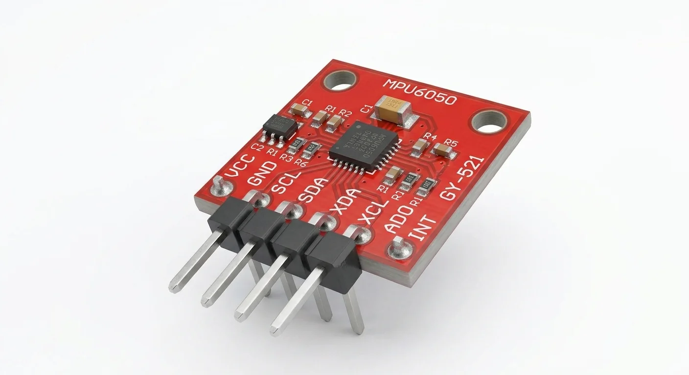
- Reference circuit: documented Adafruit MPU6050 breakout with VIN, GND, SDA, SCL and AD0. VIN accepts 3–5 V; use 3.3 V here. The approved illustration depicts a generic GY-521-style family, not this exact Adafruit board. Unknown regulators, pull-ups and header order require separate checks.
- Prerequisites and parts
- Complete IDE setup and I2C scanner lesson. Documented breakout, short wires and breadboard; secure it against shorts while moving.
- Libraries
- Install Adafruit MPU6050 2.2.6 plus Adafruit BusIO and Unified Sensor. Accept Library Manager dependencies; this release also declares GFX/SSD1306 for packaged display examples, although this sketch uses no display.
- Expected result
- Six motion axes and chip temperature print every 200 ms. A stationary sensor still measures gravity; rotation changes the gyro readings.
- Verification status
- Documentation and source review only. Not compiled or tested on hardware. The approved product-style illustration identifies a family, not a verified physical pin layout or manufacturer-authenticated board. Follow the logical diagram and documentation for your actual part.
Overview
MPU6050 combines three-axis acceleration and three-axis angular-rate sensing. Gravity is part of acceleration. It has no built-in magnetometer, so six-axis readings do not provide a drift-free compass heading.
Start with Serial values before adding displays or motion control. The Adafruit interface reports SI units; this example does not calculate position or fused orientation.
Technical Specifications
Arduino library: Adafruit MPU6050 2.2.6
| Specification | Value | Why it matters |
|---|---|---|
| Address | 0x68 default; 0x69 with AD0 HIGH | ACK alone does not establish identity. |
| Example ranges | ±2 g; ±250 degrees/s | Large motion can saturate these selected ranges. |
| Reported units | m/s²; rad/s; °C chip temperature | Not degrees/s, calibrated ambient temperature or orientation. |
Pinout
- VIN (reference breakout) Supply ESP32 3.3 V Adafruit reference; generic GY-521 needs its own schematic.
- GND Return ESP32 GND Common ground.
- SDA I2C data GPIO21 ESP32-side pull-ups to 3.3 V.
- SCL I2C clock GPIO22 100 kHz in this example.
- AD0 (reference breakout) Address select Leave at default LOW 0x68; HIGH needs a sketch change to 0x69.
- INT / auxiliary pins Unused features Not connected Polling; no auxiliary sensor.
Wiring Diagram
Reference Adafruit VIN to 3.3 V, common GND, SDA21, SCL22 and default AD0 LOW for 0x68. INT unused.
| Component terminal | ESP32 / circuit connection | Purpose and qualification |
|---|---|---|
| VIN (reference breakout) | ESP32 3.3 V | Adafruit reference; generic GY-521 needs its own schematic. |
| GND | ESP32 GND | Common ground. |
| SDA | GPIO21 | ESP32-side pull-ups to 3.3 V. |
| SCL | GPIO22 | 100 kHz in this example. |
| AD0 (reference breakout) | Leave at default LOW | 0x68; HIGH needs a sketch change to 0x69. |
| INT / auxiliary pins | Not connected | Polling; no auxiliary sensor. |
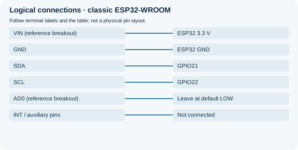
Open wiring diagram at full size (new tab)
-
1
Disconnect power and confirm actual breakout supply and pull-up rails.
-
2
Connect named reference terminals; do not infer the illustrated GY-521 header order.
-
3
Install library dependencies, upload and observe the stationary sensor before rotating it gently.
Wiring and matching Arduino code
Read motion axes and chip temperature
Reference Adafruit VIN to 3.3 V, common GND, SDA21, SCL22 and default AD0 LOW for 0x68. INT unused.
mpu6050_motion_sensor.ino
#include <Arduino.h>
#include <Wire.h>
#include <Adafruit_MPU6050.h>
#include <Adafruit_Sensor.h>
Adafruit_MPU6050 mpu;
bool ready = false;
void setup() {
  Serial.begin(115200);
  if (!Wire.begin(21, 22, 100000)) {
    Serial.println("I2C bus initialization failed");
    return;
  }
  if (!mpu.begin(0x68, &Wire)) {
    Serial.println("MPU6050 initialization failed; check wiring and AD0/address");
    return;
  }
  mpu.setAccelerometerRange(MPU6050_RANGE_2_G);
  mpu.setGyroRange(MPU6050_RANGE_250_DEG);
  mpu.setFilterBandwidth(MPU6050_BAND_21_HZ);
  ready = true;
}
void loop() {
  if (!ready) { delay(100); return; }
  sensors_event_t a, g, t;
  mpu.getEvent(&a, &g, &t);
  Serial.printf("Accel m/s^2: %.2f %.2f %.2f | Gyro rad/s: %.2f %.2f %.2f | Chip C: %.2f\n",
    a.acceleration.x, a.acceleration.y, a.acceleration.z,
    g.gyro.x, g.gyro.y, g.gyro.z, t.temperature);
  delay(200);
}
getEvent is not a robust continuous bus-health check. If disconnected after initialization, stop and diagnose instead of trusting repeated values. No fusion or calibration is performed.
Expected Output
At rest, acceleration magnitude is roughly one g (about 9.8 m/s²), distributed among axes by orientation. Gyro values may have bias near zero. These are expected relationships, not measured results. Chip temperature reflects the device and board, not calibrated air temperature.
How it works
Tilting changes gravity on each axis; rotation changes angular rate. Integrating gyro values accumulates bias and drift. Position inference from acceleration requires gravity removal and calibration; this demonstration does neither.
Troubleshooting
| Problem | Possible cause | Solution |
|---|---|---|
| Initialization fails | Wrong address, chip or wiring. | Scan the 3.3 V bus, check AD0 and actual markings; change to 0x69 only if appropriate. |
| Nonzero acceleration at rest | Gravity is included. | Compare vector magnitude and rotate the board; do not zero every axis and remove useful gravity information. |
| Gyro bias or saturation | Uncalibrated offset or range too small. | Estimate bias while still; choose a wider documented range for large motion. Do not claim compass accuracy. |
Where you use it
- Tilt and movement visualization
- Motion-input experiments
- Data for a separately designed orientation filter
Continue learning
FAQ
No. It has three acceleration and three gyro axes, without a magnetometer.
No schematic is established by this artwork. The worked circuit uses the documented Adafruit board; other regulators and pull-ups require checks.
Technical references
- Adafruit MPU6050 breakout pinouts — Reference supply, level shifting and address selection.
- Adafruit MPU6050 2.2.6 — Range/filter API, event units, initialization and dependencies.
- InvenSense MPU-6000/MPU-6050 product specification Rev. 3.4 — Manufacturer-authored document mirrored by SparkFun: axes, ranges, I2C address and bare-chip voltage. Not a generic GY-521 schematic.