
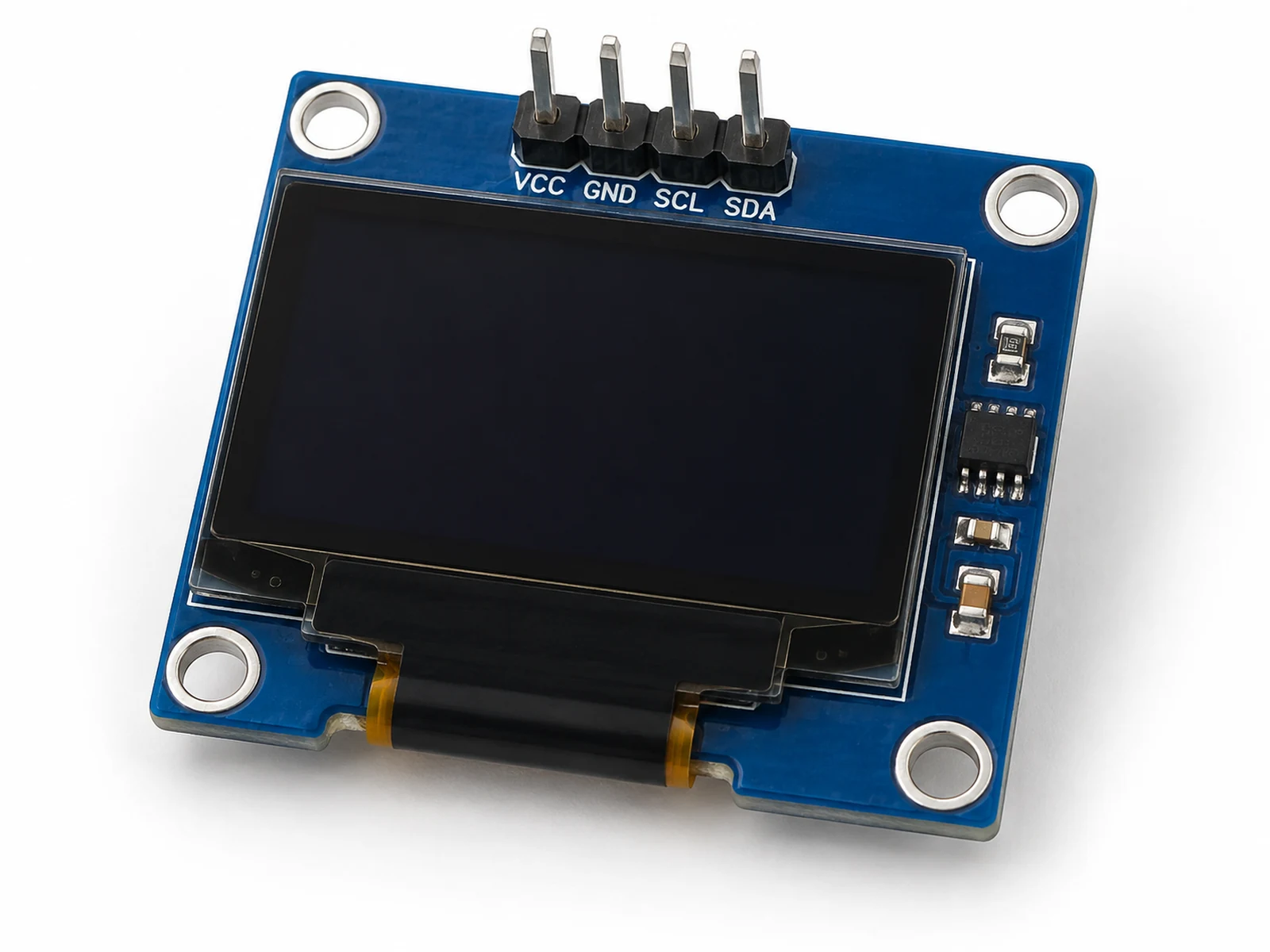
Plain-English Overview
The SSD1306 OLED is a tiny screen for your ESP32. It can show words, numbers, icons, and simple drawings without needing a computer connected.
OLED pixels make their own light, so the screen looks bright and clear. Most beginner modules are 128 pixels wide and 64 pixels tall. That sounds small, but it is enough for temperature, humidity, Wi-Fi status, battery voltage, or a simple menu.
Use it when your project needs a face. A sensor becomes much easier to understand when the value appears directly on the device.
Where You Use It
- Sensor dashboard
- Weather display
- Robot status screen
- Wi-Fi connection indicator
- Menu interface
- Battery monitor
- Classroom display demo
- Debug screen without Serial Monitor
Quick Facts
- Resolution 128 x 64 pixels
- Interface I2C on SDA/SCL
- Common address 0x3C
- Display type Monochrome OLED
- ESP32 pins GPIO21 SDA, GPIO22 SCL
- Best use Local project feedback
How It Works
The SSD1306 is a display controller chip. Your ESP32 does not control every OLED segment directly. Instead, it sends commands and screen data to the SSD1306 over I2C on the four-pin modules used in this site's beginner examples.
SSD1306 modules also exist in SPI versions with more signal pins and different code. This reference focuses on I2C modules labeled VCC, GND, SDA, and SCL. Do not copy I2C wiring onto an SPI display unless the module documentation says it supports I2C.
The display memory is like a tiny black-and-white image buffer. Libraries such as Adafruit SSD1306 let your code draw text, lines, rectangles, and pixels into a RAM buffer on the ESP32. Nothing appears until display.display() transfers that buffer to the screen.
OLED pixels emit light directly, unlike LCD pixels that need a backlight. This makes the display readable and high-contrast, but it also means static images can cause burn-in over very long periods. For learning projects, this is rarely a problem, but production devices should avoid leaving the same bright screen forever.
Because the screen shares I2C, it can live on the same SDA/SCL wires as sensors like the BME280. Each device just needs a unique address.
Technical Specifications
Arduino library: Adafruit SSD1306 plus Adafruit GFX
| Specification | Value | Why it matters |
|---|---|---|
| Resolution | 128 x 64 pixels typical | Defines how much text and graphics fit on screen. |
| Controller | SSD1306 | The chip that receives commands and drives the OLED panel. |
| Interface | I2C on most beginner modules | Keeps wiring simple with two signal wires. |
| I2C address | Usually 0x3C, sometimes 0x3D | Wrong address is the most common blank-screen cause. |
| Supply voltage | 3.3 V to 5 V on many modules | Use 3.3 V with ESP32 unless your module documentation says otherwise. |
| Logic level | 3.3 V safe on typical I2C modules | Matches ESP32 I2C signals. |
| Color | Monochrome white or blue | The library treats pixels as on/off, not full color. |
| Buffer memory | 1024 bytes for 128x64 | The ESP32 stores a screen buffer before sending it. |
| Refresh behavior | Manual display.display() update | Drawing commands update the buffer first, then the screen. |
| Viewing angle | Wide OLED viewing angle | Useful for small devices viewed from different directions. |
| Power | Depends on lit pixels | More bright pixels consume more current. |
Pinout
- VCC Power input ESP32 3.3 V Many modules accept 5 V, but 3.3 V keeps logic simple and safe.
- GND Ground reference ESP32 GND Must share ground with ESP32 and other I2C devices.
- SDA I2C data ESP32 GPIO21 Shared data line; can be used with other I2C modules.
- SCL I2C clock ESP32 GPIO22 Clock line from ESP32 I2C master.
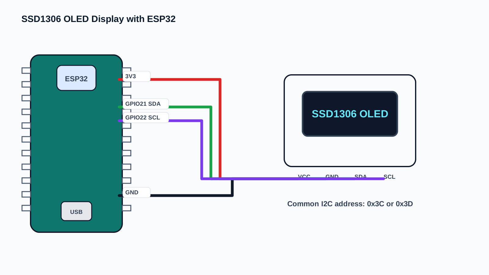
Wiring Diagram
Most SSD1306 beginner I2C modules use four pins: VCC, GND, SDA, and SCL. The display can share the same I2C bus as a BME280 sensor because each device has its own address.
Pin order, voltage regulators, and address selection vary by module. Follow the labels printed on your OLED board, use 3.3 V for this ESP32 beginner wiring, and scan the bus if the address is uncertain.
Keep wires short while learning. If the screen is blank, run an I2C scanner before changing code randomly.
| SSD1306 Pin | ESP32 Connection | Purpose / Notes |
|---|---|---|
| VCC | 3.3 V | Power for the OLED module in this beginner ESP32 wiring. Some modules allow 5 V, but do not assume that without module documentation. |
| GND | GND | Shared ground reference for the ESP32 and display. |
| SDA | GPIO21 | I2C data line used by this site's ESP32 examples; match Wire.begin(21, 22). |
| SCL | GPIO22 | I2C clock line used by this site's ESP32 examples; match Wire.begin(21, 22). |
| Address | 0x3C or 0x3D | Most modules use 0x3C and some use 0x3D. Run an I2C scanner if display.begin() fails. |
-
1
Unplug USB before wiring.
-
2
Connect OLED VCC to ESP32 3.3 V.
-
3
Connect OLED GND to ESP32 GND.
-
4
Connect OLED SDA to ESP32 GPIO21.
-
5
Connect OLED SCL to ESP32 GPIO22.
-
6
Install Adafruit SSD1306 and Adafruit GFX libraries.
-
7
Try address 0x3C first.
-
8
Open Serial Monitor to confirm whether display.begin() succeeds.
Code Examples
Use the same wiring with Arduino IDE, PlatformIO, or ESP-IDF. Start with Arduino, then graduate when you need a larger project structure.
#include <Wire.h>
#include <Adafruit_GFX.h>
#include <Adafruit_SSD1306.h>

#define SCREEN_WIDTH 128
#define SCREEN_HEIGHT 64
#define OLED_RESET -1
#define OLED_ADDRESS 0x3C

Adafruit_SSD1306 display(SCREEN_WIDTH, SCREEN_HEIGHT, &Wire, OLED_RESET);
unsigned long counter = 0;

void setup() {
  Serial.begin(115200);
  Wire.begin(21, 22);

  if (!display.begin(SSD1306_SWITCHCAPVCC, OLED_ADDRESS)) {
    Serial.println("SSD1306 not found. Check address, SDA, SCL, power, and ground.");
    while (true) delay(1000);
  }

  display.clearDisplay();
  display.setTextColor(SSD1306_WHITE);
  display.setTextSize(1);
  display.setCursor(0, 0);
  display.println("ESP32 Engine");
  display.println("OLED ready");
  display.display();
  Serial.println("OLED initialized");
}

void loop() {
  display.clearDisplay();
  display.setTextSize(1);
  display.setCursor(0, 0);
  display.println("SSD1306 OLED");
  display.println("Status: running");
  display.print("Seconds: ");
  display.println(counter++);
  display.display();
  delay(1000);
}#include <Arduino.h>
#include <Wire.h>
#include <Adafruit_GFX.h>
#include <Adafruit_SSD1306.h>
#define SCREEN_WIDTH 128
#define SCREEN_HEIGHT 64
#define OLED_RESET -1
#define OLED_ADDRESS 0x3C
Adafruit_SSD1306 display(SCREEN_WIDTH, SCREEN_HEIGHT, &Wire, OLED_RESET);
unsigned long counter = 0;
void setup() {
Serial.begin(115200);
Wire.begin(21, 22);
if (!display.begin(SSD1306_SWITCHCAPVCC, OLED_ADDRESS)) {
Serial.println("SSD1306 not found. Check address, SDA, SCL, power, and ground.");
while (true) delay(1000);
}
display.clearDisplay();
display.setTextColor(SSD1306_WHITE);
display.setTextSize(1);
display.setCursor(0, 0);
display.println("ESP32 Engine");
display.println("OLED ready");
display.display();
Serial.println("OLED initialized");
}
void loop() {
display.clearDisplay();
display.setTextSize(1);
display.setCursor(0, 0);
display.println("SSD1306 OLED");
display.println("Status: running");
display.print("Seconds: ");
display.println(counter++);
display.display();
delay(1000);
}// ESP-IDF starter structure for this component.
// Keep the wiring from the pinout section, then move the read/write logic into app_main().
#include <stdio.h>
#include "freertos/FreeRTOS.h"
#include "freertos/task.h"
void app_main(void) {
printf("SSD1306 OLED Display with ESP32 ready\n");
while (true) {
// Add component read/write code here.
vTaskDelay(pdMS_TO_TICKS(1000));
}
}Wire.begin(21, 22) starts I2C on the same GPIO21/GPIO22 pins used in this site's ESP32 examples. The display object defines the screen size and reset behavior.
setup() initializes the display and prints a clear startup screen. loop() updates a counter once per second so you can prove the screen is refreshing, not just showing a static image.
Expected Output
The OLED first shows ESP32 Engine and OLED ready. Then it refreshes once per second with a running seconds counter. Serial Monitor prints OLED initialized. If the display is blank and Serial Monitor reports not found, the address or I2C wiring is wrong.
Common Mistakes
- Using the wrong I2C address.
- Swapping SDA and SCL.
- Forgetting display.display().
- Installing Adafruit GFX but not Adafruit SSD1306.
- Using text too large for the screen.
- Powering from a noisy breadboard rail.
- Expecting color graphics on a monochrome OLED.
- Leaving static bright graphics forever in a finished device.
- Using the wrong screen height in code.
- Forgetting common ground.
Troubleshooting
| Problem | Possible cause | Solution |
|---|---|---|
| Screen stays blank | Wrong address, wiring, power, or missing display.display(). | Run I2C scanner, verify 0x3C/0x3D, and confirm SDA/SCL. |
| Code says allocation failed | Wrong display size or memory issue. | Use 128x64 or 128x32 to match your module. |
| Text appears cut off | Cursor or text size too large. | Use smaller text or reposition with setCursor(). |
| Only random pixels appear | Wrong controller, bad library settings, or poor wiring. | Confirm SSD1306 and screen size. |
| OLED works alone but not with sensor | I2C bus wiring or address issue. | Scan bus with both devices connected. |
| Display flickers | Refreshing too often or clearing unnecessarily. | Update at a slower rate and redraw only when needed. |
| Serial works but screen does not | Library init failed. | Check display.begin return value and address. |
| Screen is dim | Low contrast setting or weak power. | Use stable 3.3 V and default contrast first. |
| Upload fails after wiring | Short or wrong rail connection. | Unplug and inspect VCC/GND rows. |
| Garbled characters | Memory overwrite or wrong library. | Start from the minimal example and add code slowly. |
| Screen rotated wrong | Display orientation not set. | Use setRotation() if needed. |
| No I2C devices found | SDA/SCL swapped or no power. | Check GPIO21/GPIO22 and common ground. |
| Address conflict | Two I2C devices use same address. | Change address if hardware allows or use another device. |
| Burn-in concern | Static bright content for long periods. | Dim screen, move content, or blank when idle. |
| Works on Uno not ESP32 | Different I2C pins. | Use Wire.begin(21, 22) or wire to selected ESP32 pins. |
Related Guides
Related Projects
FAQ
SSD1306 is the display controller chip used by many small OLED modules.
Most beginner SSD1306 modules are monochrome, usually white or blue.
Most I2C modules use 0x3C; some use 0x3D.
This site's ESP32 examples use GPIO21 for SDA and GPIO22 for SCL. ESP32 I2C pins can be changed when wiring and Wire.begin(SDA, SCL) match.
Yes, if the addresses are different.
Common causes are wrong address, swapped SDA/SCL, missing power, or forgetting display.display().
Yes, Adafruit SSD1306 depends on Adafruit GFX for drawing functions.
Yes, but they must be converted to monochrome bitmaps.
Yes, but space is limited on 128x64 pixels.
No. OLED pixels emit their own light.
Long static images can age pixels, so finished devices should avoid permanent bright screens.
Usually yes for ESP32-compatible modules.
It sends the RAM buffer to the physical screen.
The library draws into memory first, then updates the screen when display.display() runs.
Yes. This page uses Adafruit libraries for beginner consistency.
Yes, but lit pixels consume power, so dim or sleep the display.
Yes, use setRotation().
It tells the library there is no separate reset pin connected.
Yes, but wiring and code are different from this I2C guide.
You need to clear the display or overwrite old text carefully.
A display buffer is memory where the library prepares pixels before sending them to the OLED.
0x3C is the common I2C address used by many SSD1306 OLED modules.
Use 3.3 V, common GND, short SDA/SCL wires, and an I2C scanner before changing display code.
Expect simple monochrome text and icons, not full-color graphics or phone-screen brightness.
It teaches I2C addressing, coordinate systems, text size, display refresh, and memory limits.
Have students record the scanned I2C address, SDA/SCL pins, text size, and when display.display() is called.
Clear the buffer before redrawing, or deliberately draw each value in a fixed rectangle.
Display one large value with a unit, then add smaller status text after the reading is stable.
Drawing commands update memory first; display.display() sends that buffer to the physical OLED.
I2C lets multiple devices share SDA and SCL when their addresses are different.
SSD1306 OLED Display with ESP32 is a displays part used with the ESP32. Learn its job first, then connect power, ground, and signal pins exactly as the wiring table shows.
A signal pin is the wire that carries information between the ESP32 and the component. It may be digital, analog, I2C, SPI, PWM, or another protocol depending on the part.
For a beginner ESP32 lesson, this component is suitable when an adult checks the wiring, keeps the project at low voltage, and unplugs USB before moving jumper wires.
Watch for reversed power pins, loose jumper wires, and children touching the circuit while it is powered. Most beginner ESP32 mistakes are wiring mistakes, not broken parts.
Use SSD1306 OLED Display with ESP32 to connect one visible hardware behavior to one software concept. Ask students to predict the reading or output first, then test it on real hardware.
Assess whether students can explain the wiring, identify the ESP32 pins used, run the example, describe the expected output, and troubleshoot one intentional mistake.
Change one variable at a time: move to another valid GPIO, adjust the timing, display the value on an OLED, or combine the component with a related project.
Disconnect one wire, predict the failure, observe the output, then explain why the failure happened before reconnecting the circuit.
Unplug USB power first. Then check the pin labels, voltage level, and ground connection before powering the ESP32 again.
Common ground gives the ESP32 and the component the same voltage reference. Without it, signal readings can be wrong or unstable.
Review, Testing, and References
Author: Abdul Mubeen and the ESP32 Engine editorial team. Last updated: 2026-08-22. Reviewed: wiring, code, beginner safety, and ESP32 compatibility. Educational level: Beginner.
Use this component page as an educational starting point. Check official documentation before using the part in production, high-current, outdoor, battery, or safety-critical hardware.
Downloads
SSD1306 controller datasheet for command details, display memory, addressing modes, and electrical behavior.
Download Datasheet (PDF)