
Before you start
- Board and software
- Classic ESP32-WROOM-32/32E DevKit with these GPIOs exposed and unused. Arduino IDE 2.x; esp32 by Espressif Systems 3.x (API review baseline 3.3.2, not a latest-version claim). Select the exact board or ESP32 Dev Module for a generic WROOM board. Other ESP32 families need their own pin map. Serial Monitor: 115200 baud.
- Hardware assumption
- One preassembled 8x8 matrix with one MAX7219, documented ISET/LED current and verified MD_MAX72XX mapping. The illustration does not establish FC-16 layout or board pin order. Use a standard 14-pin SN74AHCT125 buffer.
- Prerequisites and parts
- First complete Arduino IDE setup and Blink. Matrix, regulated 5 V supply sized for its documented load, SN74AHCT125, decoupling capacitors and short wires; no extra LEDs or individual resistors on a preassembled matrix.
- Expected result
- A diagonal lights for one second, then the display clears for one second. Orientation depends on the selected module mapping.
- Verification status
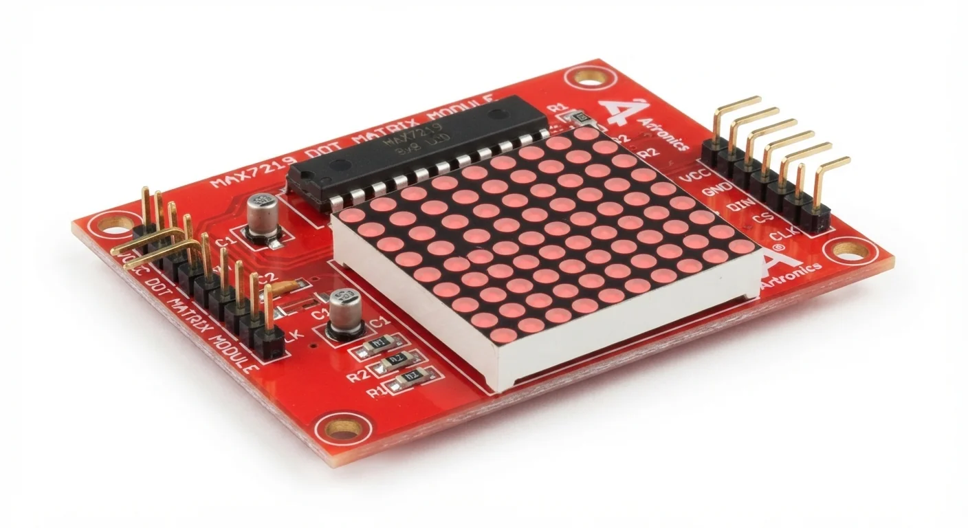
- Reviewed against the technical references below. Not compiled for an ESP32 or tested on hardware in this update. The approved product-style illustration identifies the family; follow documented terminal labels and the logical wiring diagram, not its rendered pin positions.
Overview
A MAX7219 multiplexes up to 64 LEDs, so the ESP32 sends pixel data instead of driving every LED. Start with one driver and a low intensity. A four-panel board may contain four drivers: chip count, not board count, determines MAX_DEVICES.
Supply voltage and logic voltage are separate. The driver needs regulated 5 V in this build; its specified HIGH minimum is 3.5 V. Direct ESP32 3.3 V signals are not guaranteed. Buffer DIN, CLK and LOAD through the named AHCT device, or use a module interface with documented translation.
Technical Specifications
Arduino library: MD_MAX72XX by MajicDesigns, with SPI supplied by the Arduino-ESP32 core
| Specification | Value | Why it matters |
|---|---|---|
| Driver and panel | One MAX7219; 8x8 matrix | Check chip count and module wiring. |
| Module power | Regulated 5 V | Current depends on ISET, lit pixels, intensity and driver count; no universal current budget. |
| Logic translation | SN74AHCT125 powered at 5 V | TTL-compatible inputs accept ESP32 HIGH; MAX7219 needs a higher guaranteed HIGH. |
| Decoupling | 100 nF + 10 µF near MAX7219; 100 nF at buffer | Check what the module already provides; wire power with the supply disconnected. |
| Intensity | 0–15; start at 1 | Zero is minimum brightness, not shutdown, and is not a supply current limit. |
Pinout
- VCC / V+ Supply External regulated 5 V Not ESP32 3V3; verify module label.
- GND Reference Supply minus + ESP32 GND + buffer GND Do not join independent positive power rails.
- DIN (input side) Data GPIO23 → buffer 1A pin2 / 1Y pin3 → DIN DOUT is cascade output, not the ESP32 data input.
- CLK Clock GPIO18 → buffer 2A pin5 / 2Y pin6 → CLK Short buffered connection.
- CS / LOAD Latch GPIO27 → buffer 3A pin9 / 3Y pin8 → LOAD This reference uses GPIO27; the linked project uses GPIO5 with a strapping qualification.
- Buffer power / enables 14-pin SN74AHCT125 VCC pin14 to 5 V; GND pin7 to common GND Ground OE pins1/4/10. Unused OE pin13 HIGH, input4A pin12 LOW, output4Y pin11 unconnected; verify package.
Wiring Diagram
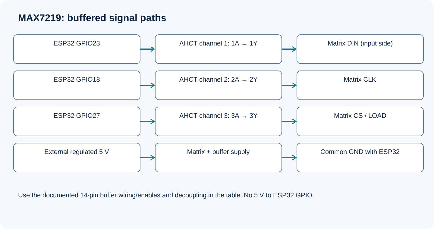
GPIO23 data, GPIO18 clock and GPIO27 LOAD go through a 5 V SN74AHCT125. Matrix/buffer power is external 5 V; grounds are shared. This is one driver, not a chain.
| Component terminal | ESP32 / circuit connection | Purpose and qualification |
|---|---|---|
| VCC / V+ | External regulated 5 V | Not ESP32 3V3; verify module label. |
| GND | Supply minus + ESP32 GND + buffer GND | Do not join independent positive power rails. |
| DIN (input side) | GPIO23 → buffer 1A pin2 / 1Y pin3 → DIN | DOUT is cascade output, not the ESP32 data input. |
| CLK | GPIO18 → buffer 2A pin5 / 2Y pin6 → CLK | Short buffered connection. |
| CS / LOAD | GPIO27 → buffer 3A pin9 / 3Y pin8 → LOAD | This reference uses GPIO27; the linked project uses GPIO5 with a strapping qualification. |
| Buffer power / enables | VCC pin14 to 5 V; GND pin7 to common GND | Ground OE pins1/4/10. Unused OE pin13 HIGH, input4A pin12 LOW, output4Y pin11 unconnected; verify package. |
Open wiring diagram at full size (new tab)
-
1
Disconnect USB and external power; identify the matrix input-side header and actual buffer package.
-
2
Wire the three buffered channels and enables exactly as the table shows. Add local decoupling and check supply capacity.
-
3
Install MD_MAX72XX by MajicDesigns in Library Manager; SPI comes with the ESP32 core. Select HARDWARE_TYPE using the library hardware guide, not the artwork.
-
4
Start at intensity 1, power the verified circuit, upload and inspect the pattern. Do not connect MAX7219 DOUT to ESP32 GPIO.
Wiring and matching Arduino code
One-driver diagonal test
GPIO23 data, GPIO18 clock and GPIO27 LOAD go through a 5 V SN74AHCT125. Matrix/buffer power is external 5 V; grounds are shared. This is one driver, not a chain.
max7219_led_matrix_esp32.ino
#include <Arduino.h>
#include <MD_MAX72xx.h>
#include <SPI.h>

// Replace GENERIC_HW with the type verified for your module.
constexpr auto HARDWARE_TYPE = MD_MAX72XX::GENERIC_HW;
constexpr uint8_t DIN_PIN = 23, CLK_PIN = 18, LOAD_PIN = 27;
constexpr uint8_t MAX_DEVICES = 1;
MD_MAX72XX matrix(HARDWARE_TYPE, DIN_PIN, CLK_PIN, LOAD_PIN, MAX_DEVICES);
bool ready = false;

void setup() {
  Serial.begin(115200);
  ready = matrix.begin();
  if (!ready) { Serial.println("Library initialization failed."); return; }
  matrix.control(MD_MAX72XX::INTENSITY, 1);
  matrix.clear();
  Serial.println("Diagonal test; verify module mapping and buffered wiring.");
}
void loop() {
  if (!ready) { delay(1000); return; }
  for (uint8_t i = 0; i < 8; ++i) matrix.setPoint(i, i, true);
  delay(1000);
  matrix.clear();
  delay(1000);
}
begin() reports library initialization, not a sensor-style hardware identity or wiring test. GENERIC_HW is a configurable example, not a claim about the supplied illustration. For text/scrolling use the linked project and verified module mapping.
Expected Output
Eight diagonal pixels should light for about one second and clear for one second. A different orientation is possible until mapping is correct. A successful library message does not prove power or data wiring. Start with the simple pattern before adding scrolling text.
How it works
The library sends pixel data through the three named software-interface pins and the driver refreshes the display. Verify module layout in MD_MAX72XX before judging orientation. The supply must support the configured LED load; increasing intensity is not a repair for unstable power.
Troubleshooting
| Problem | Possible cause | Solution |
|---|---|---|
| No pixels | Wrong header, missing power/ground or LOAD wiring. | Check the regulated supply, input DIN, buffered channels, enabled outputs and chip count. |
| Random pixels or resets | Supply droop, long wiring or direct 3.3 V control. | Use the specified buffer, short wires and decoupling; check the supply under load. |
| Mirrored or rotated pattern | Wrong hardware mapping or panel orientation. | Choose the documented MD_MAX72XX module type; do not assume every board is FC-16. |
| Missing MD_MAX72xx.h | Library absent or include case differs. | Install MD_MAX72XX by MajicDesigns; keep the exact header spelling shown. |
Where you use it
- LED status panel
- Small clock display
- Scrolling message board
Continue learning
Related projects
FAQ
This build uses regulated 5 V. MAX7219 specifies 4.0–5.5 V operation; another driver or translated module needs its own documentation.
No. It selects minimum intensity. Clear the pixels or use the library shutdown control for a blank display.
No. It is a product-style illustration. Use documented header labels, buffer package pins and the wiring table.
Technical references
- Analog Devices MAX7219/MAX7221 datasheet — Supply, input thresholds, LED-current setting and decoupling.
- TI SN74AHCT125 datasheet — TTL input levels, enables and package-specific connections.
- MD_MAX72XX API — Explicit software-interface constructor, begin, intensity and setPoint.
- MD_MAX72XX hardware guide — Select actual module wiring; layouts differ.
Downloads
Official manufacturer PDF for teachers and advanced builders.
No separate datasheet is needed for this beginner guide.