
Before you start
- Board and software
- Classic ESP32-WROOM-32/32E DevKit with the listed GPIOs exposed and unused. Arduino IDE 2.x; esp32 by Espressif Systems 3.3.2 (review baseline, not a latest-release claim). Select the documented board or ESP32 Dev Module for a generic WROOM board. Other families need their own pin map. Serial Monitor: 115200 baud.
- Supported hardware
- Bare Vishay TSOP38238, not an arbitrary IR module. Vishay numbers leads 1 OUT, 2 GND, 3 VS; confirm orientation in its package drawing.
- Prerequisites and parts
- Complete IDE setup and Blink. Receiver, short wires, 100 nF ceramic bypass capacitor and a known 38 kHz remote with working batteries.
- Libraries
- Install IRremote by Armin Joachimsmeyer 4.4.1. Use IRremote.hpp, not legacy IRremote.h examples. The pinned library includes an ESP32 3.x timer branch.
- Expected result
- Serial prints protocol/address/command information for decodable frames. Unsupported patterns can appear UNKNOWN; held keys can produce repeats.
- Verification status
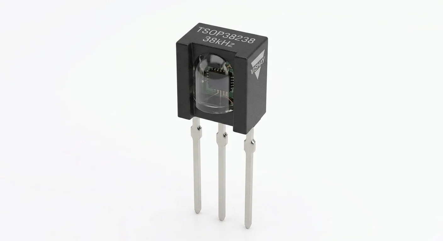
- Documentation and source review only. Not compiled or tested on hardware. The approved product-style illustration identifies a family, not a verified physical pin layout or manufacturer-authenticated board. Follow the logical diagram and documentation for your actual part.
Overview
The receiver filters infrared bursts near 38 kHz and outputs their envelope as active-LOW pulses. It is not a raw photodiode, obstacle sensor or transmitter. A protocol decoder interprets the pulse pattern.
Use a known compatible remote first. Decoding depends on protocol, lighting and placement; the artwork cannot establish the authenticity of a physical part.
Technical Specifications
Arduino library: Arduino-IRremote 4.4.1
| Specification | Value | Why it matters |
|---|---|---|
| Carrier | 38 kHz nominal | Other carrier frequencies are not assumed compatible. |
| Output | Demodulated active-LOW pulses | Not a steady button state. |
| Pin numbering | 1 OUT; 2 GND; 3 VS | Use the manufacturer package view, not another receiver’s pin order. |
Pinout
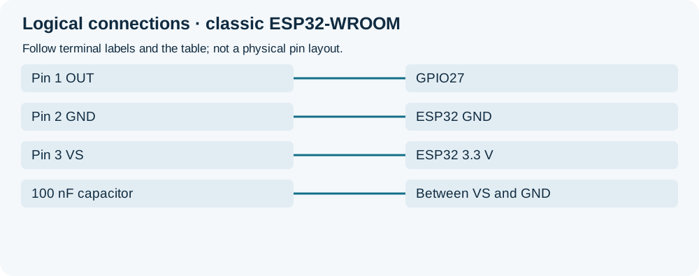
- Pin 1 OUT Signal GPIO27 Match the numbered manufacturer package view.
- Pin 2 GND Return ESP32 GND Common ground.
- Pin 3 VS Supply ESP32 3.3 V No 5 V supply in this circuit.
- 100 nF capacitor Bypass Between VS and GND Unpolarized ceramic; close to receiver.
Wiring Diagram
Pin1 OUT to GPIO27, pin2 GND to GND, pin3 VS to 3.3 V; 100 nF across VS/GND.
| Component terminal | ESP32 / circuit connection | Purpose and qualification |
|---|---|---|
| Pin 1 OUT | GPIO27 | Match the numbered manufacturer package view. |
| Pin 2 GND | ESP32 GND | Common ground. |
| Pin 3 VS | ESP32 3.3 V | No 5 V supply in this circuit. |
| 100 nF capacitor | Between VS and GND | Unpolarized ceramic; close to receiver. |
Open wiring diagram at full size (new tab)
-
1
Disconnect USB; identify the exact receiver and check numbered package orientation.
-
2
Connect the named leads and capacitor; install IRremote 4.4.1.
-
3
Upload, open Serial Monitor at 115200 and aim a compatible remote at the receiver.
Wiring and matching Arduino code
Receive and print decoded frames
Pin1 OUT to GPIO27, pin2 GND to GND, pin3 VS to 3.3 V; 100 nF across VS/GND.
tsop38238_ir_receiver.ino
#include <Arduino.h>
#include <IRremote.hpp>
constexpr uint8_t IR_PIN = 27;
void setup() {
  Serial.begin(115200);
  IrReceiver.begin(IR_PIN, DISABLE_LED_FEEDBACK);
  Serial.println("Aim a compatible 38 kHz remote and press a key");
}
void loop() {
  if (IrReceiver.decode()) {
    IrReceiver.printIRResultShort(&Serial);
    IrReceiver.resume();
  }
}
Feedback is disabled so no onboard LED is assumed. Resume reception after each frame. Test alone before adding code that blocks interrupts and interferes with timing.
Expected Output
Supported protocols produce decoded fields, not a universal button number. UNKNOWN need not mean a defective receiver. Repeated frames while holding a key are normal for many remotes.
How it works
The receiver removes the optical carrier. IRremote samples the envelope with a timer and attempts supported decoders. Bright illumination and supply noise can reduce reception.
Troubleshooting
| Problem | Possible cause | Solution |
|---|---|---|
| Nothing prints after startup | Wrong lead order, remote batteries or carrier mismatch. | Recheck the package view and 3.3 V; try a known 38 kHz remote close to the receiver. |
| UNKNOWN or unreliable frames | Protocol mismatch, strong illumination or timing noise. | Shade the receiver, check bypassing and short wires; test without interrupt-blocking additions. |
| Legacy sketch will not compile | Old IRremote API mixed with version 4.4.1. | Use IRremote.hpp and IrReceiver begin/decode/resume; confirm the selected library version. |
Where you use it
- Remote-controlled low-voltage indicator
- Protocol exploration
- Alternative input to a push button
Continue learning
FAQ
The remote sends pulse frames. Decode them rather than treating OUT as a mechanical switch.
No. This diagram is for the documented TSOP38238 package; check your actual part or module.
Technical references
- Vishay TSOP382.. datasheet — Pin numbering, supply, demodulation and disturbance guidance.
- IRremote 4.4.1 — Receive API and protocols.
- IRremote 4.4.1 ESP32 timer code — Core 3.x branch reviewed; not compiled.