
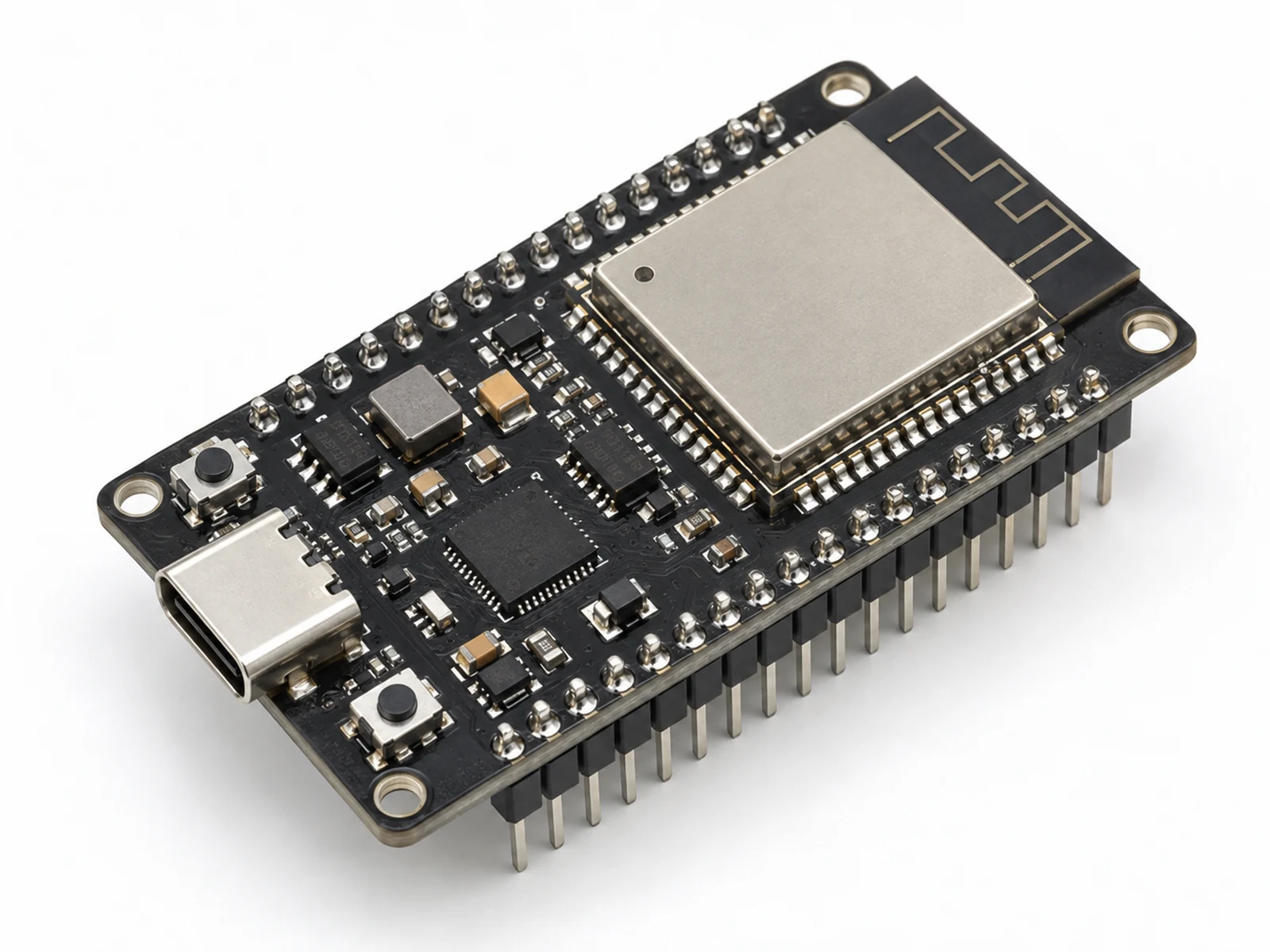
Plain-English Overview
The ESP32 DevKit is the brain of your project. It is a small computer board that plugs into USB, runs Arduino sketches, connects to Wi-Fi or Bluetooth, and uses GPIO pins to read sensors, buttons, displays, LEDs, relays, and motor drivers.
"ESP32 DevKit" is a broad name used for several development boards. This page focuses on common classic ESP32-WROOM DevKit and DevKit V1-style boards. Exact silkscreen labels, USB chips, onboard LEDs, flash size, and physical pin positions can vary by manufacturer, so follow GPIO numbers and your board's pin labels instead of assuming every DevKit is identical.
Use this page as a practical ESP32 DevKit pinout and setup hub: what the board can do, which pins are good beginner choices for many projects, which pins need caution, how 3.3 V logic works, how to upload your first sketch, and where ADC, PWM, I2C, SPI, Wi-Fi, and Bluetooth fit.
Where You Use It
- First ESP32 learning board
- Wi-Fi sensor node
- Bluetooth controller
- Robot brain
- Home automation prototype
- Classroom lab board
- MQTT device
- Low-cost IoT gateway
Quick Facts
- Brain Classic ESP32-WROOM module on common DevKit boards
- Logic level 3.3 V GPIO
- Programming USB to serial
- Wireless 2.4 GHz Wi-Fi plus Bluetooth/BLE
- Best start ESP32-WROOM DevKit
- Arduino support ESP32 board package
How It Works
The DevKit combines a classic ESP32 module with the support electronics needed for learning. USB power enters the board, an onboard regulator creates 3.3 V for the ESP32, and a USB-to-serial chip such as CP210x or CH340 converts computer USB signals into UART signals the ESP32 bootloader understands. The exact USB chip depends on the board.
When you click Upload, Arduino IDE compiles your sketch and sends it through USB. The board enters bootloader mode, writes firmware into flash memory, then resets and starts running your program. Some boards enter bootloader mode automatically; others need the BOOT button if upload stays on Connecting.
GPIO pins are programmable signal connections to the outside world. On common classic ESP32 boards, many pins can read digital inputs, drive digital outputs, generate LEDC PWM, read analog voltage, or join I2C, SPI, and UART buses. The key engineering rule is that GPIO pins are signal pins, not power supplies. They can control modules, but motors, pumps, large LED loads, and heavy relays need drivers, modules, and suitable low-voltage load supplies.
The wireless radio shares power with the rest of the board. When Wi-Fi transmits, current briefly rises. Weak USB cables, poor breadboards, overloaded 3.3 V rails, or missing shared grounds can cause resets and confusing readings.
Technical Specifications
Arduino library: Arduino ESP32 board package
| Specification | Value | Why it matters |
|---|---|---|
| Main chip | ESP32-WROOM family on most DevKit boards | This is the common module used by most beginner tutorials. |
| CPU | Dual-core Tensilica LX6 up to 240 MHz on common classic ESP32 | Enough processing power for sensors, displays, networking, and control logic. |
| Logic voltage | 3.3 V | GPIO pins must not be driven with 5 V signals. |
| USB input | 5 V from USB | USB powers the board and provides the programming connection. |
| Wireless | 2.4 GHz Wi-Fi 802.11 b/g/n and Bluetooth/BLE | Allows web dashboards, MQTT, phone control, and wireless data logging. |
| Flash | Often 4 MB on common DevKit V1-style boards | Stores firmware and sometimes file-system data, but exact flash size is not guaranteed. |
| SRAM | About 520 KB internal SRAM | Enough for beginner projects; large web apps and images require care. |
| ADC | ADC1 and ADC2-capable pins on classic ESP32 | Use ADC1 where practical for Wi-Fi projects because ADC2 is restricted while Wi-Fi is active. |
| PWM | LEDC PWM on many GPIOs | Controls LED brightness, buzzers, servos, and motor drivers. |
| I2C | Software-selectable pins; default GPIO21 SDA, GPIO22 SCL | Shares two wires with sensors and displays. |
| SPI | Hardware SPI buses available; chosen pins can vary | Useful for fast displays, SD cards, and radio modules when the pins match your board and library. |
| Safe current | GPIO signals are 3.3 V and not 5 V tolerant | Protects the ESP32 from overheating, boot failure, or permanent damage. |
Pinout
- 5V / VIN USB power rail 5 V modules or board input Not a GPIO. Use carefully and do not feed 5 V into signal pins.
- 3V3 Regulated output Small 3.3 V modules Limited current and board-dependent. Do not power motors, pumps, relays, or large LED loads from this pin.
- GND Ground reference All signal-sharing circuits Most external sensors, drivers, and modules need a shared ground/reference with the ESP32.
- EN Enable/reset Usually left alone Pulling EN low resets the chip.
- GPIO0 Boot strapping pin Avoid for first projects Holding it low during reset enters bootloader mode.
- GPIO2 GPIO with boot considerations LED examples on some boards Can affect boot on some boards; use carefully.
- GPIO4, 5, 16, 17, 18, 19, 21, 22, 23 General GPIO Sensors and outputs Good beginner choices for many projects when they are not already used by your board or shield.
- GPIO25, 26, 27, 32, 33 GPIO with ADC support Analog sensors or digital signals Useful classic ESP32 choices when you want ADC1 analog input and Wi-Fi in the same project.
- GPIO21 Default I2C SDA OLED/BME280 SDA Common default for I2C examples; I2C pins are configurable in code.
- GPIO22 Default I2C SCL OLED/BME280 SCL Common default clock line for I2C examples; not the only possible SCL pin.
- GPIO34-39 Input-only pins Externally driven analog or digital inputs Classic ESP32 input-only pins. They cannot drive LEDs, relays, motors, or other outputs and have no internal pull-up or pull-down resistors.
- GPIO32-39 Common ADC1 pins Analog sensors Prefer ADC1 for Wi-Fi sensor projects on classic ESP32 because ADC2 is restricted while Wi-Fi is active.
- TX0/RX0 USB serial pins Programming/logging Avoid using them for beginner circuits while debugging over USB.
- GPIO0, GPIO2, GPIO12, GPIO15 Boot strapping pins Avoid for first projects External wiring can hold the wrong level during reset and prevent boot on classic ESP32 boards.
Wiring Diagram
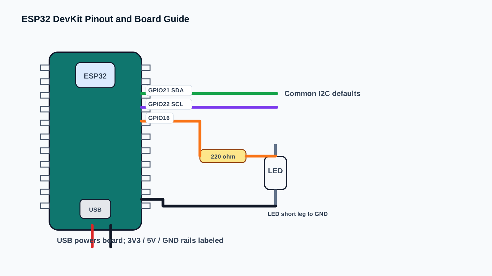
Start with one safe output circuit before connecting complex modules. Use USB for board power, keep GPIO signals within 3.3 V logic levels, connect shared ground where signals cross between boards, and never connect 5 V signals directly to ESP32 GPIO pins.
ESP32 DevKit variants differ. The table below summarizes practical beginner connections for common classic ESP32-WROOM DevKit and DevKit V1-style boards, but you should still follow the GPIO numbers and labels printed on your exact board.
An external LED on GPIO16 is more portable than assuming every DevKit has the same onboard LED. It teaches the most important pattern: GPIO drives a small signal, a resistor limits current, and ground completes the circuit.
| DevKit Pin / Feature | Beginner Use | Purpose / Notes |
|---|---|---|
| USB | Programming and 5 V input | Uploads sketches, powers beginner projects, and opens Serial Monitor. Use a data cable, not a charge-only cable. |
| 3V3 | Small 3.3 V modules | Use for low-current sensors and displays. Current limit depends on the board regulator. |
| 5V / VIN | USB/input rail | Not a GPIO. Do not feed this voltage into ESP32 signal pins. |
| GND | Common ground | Connect to every module that exchanges signals with the ESP32. |
| GPIO16 | External LED test | Portable first output choice for this page; do not assume every board's onboard LED uses the same GPIO. |
| GPIO21 / GPIO22 | I2C SDA / SCL defaults | Common Arduino ESP32 defaults for OLED and BME280 examples; I2C pins are configurable in code. |
| GPIO34-GPIO39 | Input-only | Classic ESP32 input-only pins. They cannot drive outputs and do not provide internal pull-up or pull-down resistors. |
| GPIO0, GPIO2, GPIO12, GPIO15 | Boot strapping pins | Avoid for first projects because external wiring can affect boot mode. |
-
1
Unplug USB before wiring.
-
2
Place the ESP32 DevKit so each side of pins sits on a different breadboard half.
-
3
Install the ESP32 board package in Arduino IDE.
-
4
Connect the board with a known USB data cable, not a charge-only cable.
-
5
Select the appropriate ESP32 board profile and the correct COM/serial port.
-
6
Connect a 220 ohm resistor from GPIO16 to the LED long leg.
-
7
Connect the LED short leg to GND.
-
8
Upload the blink code and confirm the external LED changes state.
-
9
If upload stays on Connecting, hold BOOT while upload begins, then release when writing starts.
-
10
Open Serial Monitor at 115200 baud to confirm the sketch is running.
-
11
For sensors, connect VCC to the voltage required by that component and keep any signal into ESP32 GPIO at 3.3 V logic.
-
12
Always connect module GND to ESP32 GND when the module exchanges signals with the board.
Code Examples
Use the same wiring with Arduino IDE, PlatformIO, or ESP-IDF. Start with Arduino, then graduate when you need a larger project structure.
#define LED_PIN 16

void setup() {
  Serial.begin(115200);
  pinMode(LED_PIN, OUTPUT);
  Serial.println("ESP32 DevKit external LED blink test started");
}

void loop() {
  digitalWrite(LED_PIN, HIGH);
  Serial.println("LED ON");
  delay(500);

  digitalWrite(LED_PIN, LOW);
  Serial.println("LED OFF");
  delay(500);
}#include <Arduino.h>
#define LED_PIN 16
void setup() {
Serial.begin(115200);
pinMode(LED_PIN, OUTPUT);
Serial.println("ESP32 DevKit external LED blink test started");
}
void loop() {
digitalWrite(LED_PIN, HIGH);
Serial.println("LED ON");
delay(500);
digitalWrite(LED_PIN, LOW);
Serial.println("LED OFF");
delay(500);
}// ESP-IDF starter structure for this component.
// Keep the wiring from the pinout section, then move the read/write logic into app_main().
#include <stdio.h>
#include "freertos/FreeRTOS.h"
#include "freertos/task.h"
void app_main(void) {
printf("ESP32 DevKit Pinout and Board Guide ready\n");
while (true) {
// Add component read/write code here.
vTaskDelay(pdMS_TO_TICKS(1000));
}
}This sketch proves that the board, USB cable, Arduino setup, selected port, Serial Monitor, and one GPIO pin all work.
setup() runs once and configures GPIO16 as an output for an external LED. loop() toggles the pin without using any external libraries. GPIO16 is a good beginner choice for many DevKit projects, but you can move LED_PIN to another suitable output GPIO if your board or shield already uses it.
Expected Output
Serial Monitor at 115200 baud prints LED ON and LED OFF every half second. The external LED on GPIO16 should blink at the same rhythm. Some DevKit boards also have an onboard LED, but the exact onboard LED pin varies by board.
Common Mistakes
- Using a charge-only USB cable.
- Selecting the wrong COM port.
- Forgetting to install the ESP32 board package.
- Treating VIN/5V as a signal pin or feeding 5 V directly into GPIO.
- Powering motors, pumps, relay coils, or large LED loads from GPIO or the 3V3 pin.
- Forgetting shared ground/reference between the ESP32 and an external signal module.
- Using GPIO34-GPIO39 as outputs or relying on internal pull-ups/pull-downs on those pins.
- Using boot strapping pins without understanding startup behavior.
- Expecting all ESP32 DevKit boards to have the same onboard LED, flash size, USB chip, or pin layout.
- Letting Wi-Fi current spikes brown out a weak USB power source.
Troubleshooting
| Problem | Possible cause | Solution |
|---|---|---|
| Board not detected | USB cable is charge-only, driver missing, or wrong port. | Use a known data cable, install CP210x/CH340 drivers if needed, and select the correct port. |
| Upload stuck on Connecting | Board did not enter bootloader mode. | Hold BOOT while upload begins, then release when writing starts. |
| Sketch uploads but nothing happens | Wrong GPIO, LED polarity, or resistor row. | Check LED long leg, GND, resistor placement, and LED_PIN value. Follow GPIO numbers, not only physical pin position. |
| Serial output is unreadable | Baud rate mismatch. | Set Serial Monitor to 115200 baud. |
| Board resets when Wi-Fi starts | Weak USB supply or overloaded 3.3 V rail. | Use a better USB cable and do not power heavy loads from the board. |
| Sensor gives nonsense | No common ground, wrong voltage, or 5 V signal into a 3.3 V GPIO. | Share GND where signals cross between boards, verify the component voltage requirement, and level-shift 5 V signals before ESP32 GPIO. |
| GPIO will not output | You used input-only GPIO34-GPIO39. | Move output wiring to a normal GPIO such as 4, 16, 17, 18, 19, 21, 22, or 23. Use GPIO34-GPIO39 only for externally driven inputs. |
| Board will not boot after wiring | A strapping pin is pulled to the wrong level. | Disconnect external wiring, boot again, and avoid GPIO0, GPIO2, GPIO12, GPIO15 for beginner circuits. |
| Arduino IDE has no ESP32 boards | Board package URL not installed. | Install the Espressif ESP32 package in Boards Manager. |
| Port disappears during upload | USB cable/connector is loose or power dips. | Use a short cable and avoid moving the board while uploading. |
| Pin labels do not match tutorial | Different DevKit layouts use different printed labels. | Follow GPIO numbers, not physical pin position. |
| Analog read changes with Wi-Fi | ADC2 pins are affected by Wi-Fi on classic ESP32. | Use ADC1 pins such as GPIO32-GPIO39 for analog sensors in Wi-Fi projects on classic ESP32. |
| Relay or motor does not work directly | GPIO cannot supply enough current. | Use a relay module, MOSFET, transistor, or motor driver. |
| Board gets hot | Short circuit or overloaded regulator. | Unplug immediately and inspect 5 V, 3.3 V, and GND wiring. |
| Random crashes | Floating input, memory issue, unstable power, or a strapping pin held at the wrong level. | Use pull-ups/pull-downs where available, add external resistors for GPIO34-GPIO39 inputs, simplify code, and check power and boot-pin wiring. |
Related Guides
Related Projects
FAQ
Choose a common ESP32-WROOM DevKit or DevKit V1-style board with USB, labeled GPIO numbers, and good documentation.
No. ESP32 is a microcontroller, but it can be programmed using Arduino IDE.
Only if the signal into GPIO is shifted to 3.3 V. ESP32 GPIO pins are not 5 V tolerant.
USB provides 5 V to the board, and the onboard regulator creates 3.3 V for the ESP32.
No. Use a motor driver and separate power supply with common ground.
They are all ground references. Use any convenient GND pin.
GPIO means general-purpose input/output, a pin your code can read or control.
GPIO4, 5, 16, 17, 18, 19, 21, 22, 23, 25, 26, and 27 are good beginner choices for many projects when they are not already used by your board or shield.
Avoid strapping pins such as GPIO0, GPIO2, GPIO12, and GPIO15 until you understand boot behavior.
Some boards do not auto-enter bootloader mode reliably, so BOOT forces it.
EN is the enable/reset pin. Pulling it low resets the ESP32.
Yes. Common classic ESP32 DevKit boards include 2.4 GHz Wi-Fi.
Classic ESP32 supports Bluetooth and BLE, though support varies on newer ESP32 families.
Common causes are weak USB power, wiring shorts, heavy loads, or unstable code.
Yes. ESP32 supports MicroPython, but ESP32 Engine beginner content uses Arduino first.
Flash stores your uploaded program and sometimes files. Many common DevKit boards have 4 MB, but exact flash size varies.
VIN/5V is the USB/input rail. 3V3 is regulated output for the ESP32 and small sensors.
Yes, but choose the right regulator and use deep sleep for long life.
ESP32 ADC is useful but not laboratory-grade. On classic ESP32, ADC2 use is restricted while Wi-Fi is active, so prefer ADC1 pins for Wi-Fi sensor projects.
No. On classic ESP32, GPIO34-GPIO39 are input-only and have no internal pull-up or pull-down resistors. Use them for properly driven analog or digital inputs, not outputs.
No. They are common Arduino ESP32 defaults for SDA and SCL on many DevKit examples, but ESP32 I2C pins are configurable in code.
No. Some boards have an onboard LED and some do not, and the LED GPIO can vary. An external LED on a known GPIO is more portable for first tests.
Yes, if addresses are unique and wiring stays short and clean.
A DevKit is a development board that adds USB programming, voltage regulation, buttons, and header pins around the ESP32 module.
A strapping pin is sampled during reset to choose boot behavior, so external wiring can stop the board from starting.
Use USB power, an external LED with a resistor, and Serial Monitor before adding sensors, relays, motors, or Wi-Fi loads.
Unplug if the board gets hot, a wire shorts 5 V to 3.3 V/GND, or a 5 V signal is connected to GPIO.
It teaches board setup, GPIO naming, power rails, upload mode, safe pin choices, and debugging habits.
Have students upload blink, read Serial Monitor, identify GND/3V3/5V, and explain why GPIO is not a power supply.
Pick a normal GPIO, avoid strapping pins for first projects, and avoid GPIO34-GPIO39 for outputs.
Test board upload, power, ground, one signal pin, and Serial Monitor before combining multiple modules.
Signals need the same voltage reference, so the ESP32 and module must share GND when they exchange signals.
Classic ESP32 GPIO pins are 3.3 V logic and are not 5 V tolerant.
ESP32 DevKit Pinout and Board Guide is a boards part used with the ESP32. Learn its job first, then connect power, ground, and signal pins exactly as the wiring table shows.
A signal pin is the wire that carries information between the ESP32 and the component. It may be digital, analog, I2C, SPI, PWM, or another protocol depending on the part.
For a beginner ESP32 lesson, this component is suitable when an adult checks the wiring, keeps the project at low voltage, and unplugs USB before moving jumper wires.
Watch for reversed power pins, loose jumper wires, and children touching the circuit while it is powered. Most beginner ESP32 mistakes are wiring mistakes, not broken parts.
Use ESP32 DevKit Pinout and Board Guide to connect one visible hardware behavior to one software concept. Ask students to predict the reading or output first, then test it on real hardware.
Assess whether students can explain the wiring, identify the ESP32 pins used, run the example, describe the expected output, and troubleshoot one intentional mistake.
Change one variable at a time: move to another valid GPIO, adjust the timing, display the value on an OLED, or combine the component with a related project.
Disconnect one wire, predict the failure, observe the output, then explain why the failure happened before reconnecting the circuit.
Unplug USB power first. Then check the pin labels, voltage level, and ground connection before powering the ESP32 again.
Common ground gives the ESP32 and the component the same voltage reference. Without it, signal readings can be wrong or unstable.
Review, Testing, and References
Author: Abdul Mubeen and the ESP32 Engine editorial team. Last updated: 2026-08-22. Reviewed: wiring, code, beginner safety, and ESP32 compatibility. Educational level: Beginner.
Use this component page as an educational starting point. Check official documentation before using the part in production, high-current, outdoor, battery, or safety-critical hardware.
Downloads
Espressif ESP32-WROOM datasheet for electrical limits, RF details, memory, boot pins, and module ratings.
Download Datasheet (PDF)