
Before you start
- Board and software
- Low-voltage bench setup as specified below. ESP32 is optional for passive exercises. Coded examples require classic ESP32-WROOM-32/32E DevKit, unused exposed pins, Arduino IDE 2.x and Arduino-ESP32 3.3.2 (review baseline, not a latest-release claim). Other families need their own pin map.
- Supported hardware
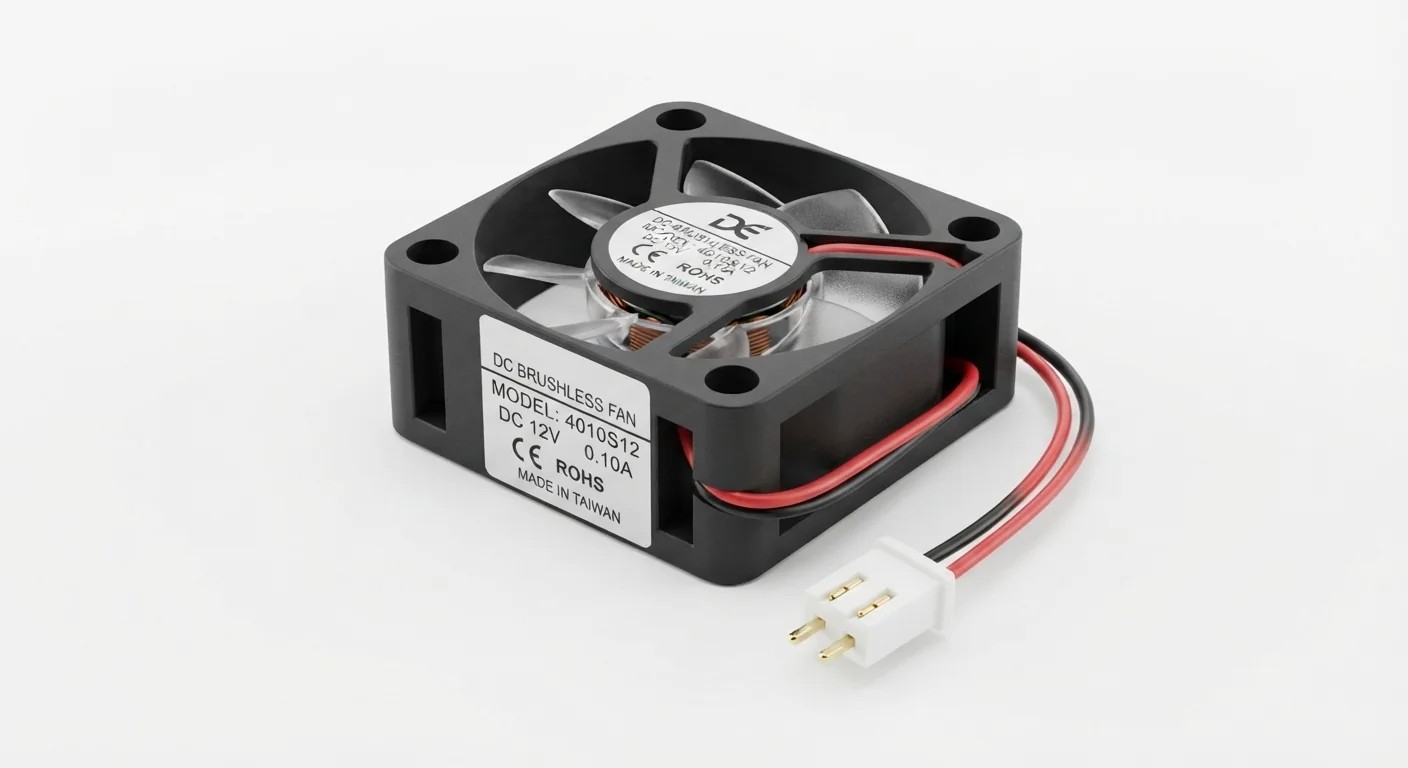
- Approved illustration shows DC12V brushless fan, not a verified model or current rating. Worked reference: Noctua NF-A4x10 FLX, a documented 12 V three-wire fan; artwork is not this reference model.
- Prerequisites and parts
- Reference fan, matching current-limited 12 V DC supply and suitable insulated connections. Read actual connector documentation. Keep blades clear; no ESP32 or breadboard motor-power path needed.
- Libraries
- No firmware or library required for this exercise. Arduino-ESP32 3.3.2 is the site review baseline, not a dependency of this passive setup.
- Expected result
- A documented fan spins when its rated supply is applied; no speed or airflow measurement is claimed.
- Verification status
- Documentation and source review only. Not compiled or tested on hardware. The approved product-style illustration identifies a family, not a verified physical pin layout or manufacturer-authenticated board. Follow the logical diagram and documentation for your actual part.
Overview
A brushless cooling fan includes its own commutation electronics. Its supply rating is not a GPIO voltage. The approved picture identifies a 12 V fan family; it cannot establish current, connector order, airflow or PWM support.
The worked reference has power, ground and a tachometer lead. Leave tachometer disconnected for the first constant-power test. Two-, three- and four-wire fans are different interfaces; wire color alone is not a pinout. Do not reverse supply to reverse rotation.
Technical Specifications
Arduino library: No firmware or library required for this exercise
| Specification | Value | Why it matters |
|---|---|---|
| Illustration label | DC12V | Model/current and lead order remain unverified. |
| Worked reference | NF-A4x10 FLX at 12 V | Only that documented model; not a universal fan specification. |
Pinout
- Documented fan power terminal Connection Rated external +12 V Reference model only; verify connector.
- Documented fan ground Connection Supply negative Do not infer by illustration position.
- Tachometer (reference third wire) Connection Leave disconnected No GPIO in this exercise.
- ESP32 GPIO / 3V3 Connection No fan connection Separate load power required.
Wiring Diagram
Rated DC supply connects only to identified fan power/ground; other leads unconnected.
| Component terminal | ESP32 / circuit connection | Purpose and qualification |
|---|---|---|
| Documented fan power terminal | Rated external +12 V | Reference model only; verify connector. |
| Documented fan ground | Supply negative | Do not infer by illustration position. |
| Tachometer (reference third wire) | Leave disconnected | No GPIO in this exercise. |
| ESP32 GPIO / 3V3 | No fan connection | Separate load power required. |
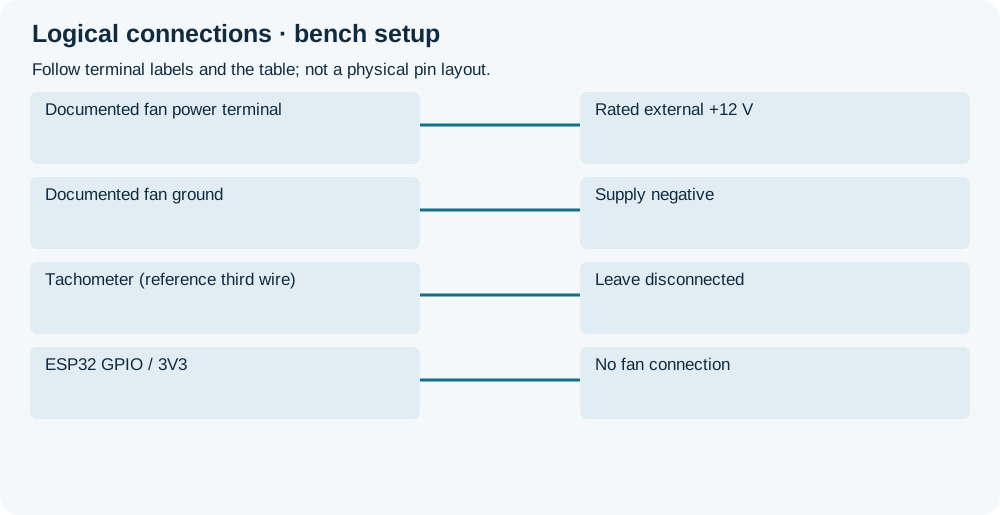
Open wiring diagram at full size (new tab)
-
1
Remove power, verify model, rated supply and connector drawing.
-
2
Connect the two power terminals using appropriate wiring; leave tachometer insulated.
-
3
Apply rated supply briefly, observe free rotation, then disconnect before changes.
Expected Output
With correct rated power the unloaded fan should spin. A stationary fan, noise or overheating is a reason to disconnect and inspect, not increase voltage.
How it works
A constant supply powers the fan internal controller. For ESP32 switching, use a suitably rated driver and its complete power/protection circuit; do not copy a bare brushed-motor flyback circuit without checking fan/driver requirements. A four-wire PWM input is separate from switching the fan supply.
A future non-isolated ESP32 control driver needs a common signal ground between ESP32 and fan supply, with fan current returning directly to that supply. Verify startup current and driver transient protection from the actual fan/driver documentation. A brushless fan has internal electronics; do not apply bare-motor stall-current or flyback assumptions blindly. The separate constant-power exercise has no ESP32 connection.
Troubleshooting
| Problem | Possible cause | Solution |
|---|---|---|
| No rotation | Wrong polarity, supply/current limit or obstructed rotor. | Disconnect power, verify connector/rating and clear obstruction. |
| ESP32 resets | Fan current taken from board supply. | Use suitable external supply and a reviewed driver circuit before connecting any control. |
| Extra wire unidentified | Tach/PWM role assumed by color. | Leave it disconnected until model documentation establishes interface and voltage. |
Where you use it
- Enclosure cooling with a documented fan
- Learning separate load power before adding control
FAQ
No. GPIO is a logic output, not the fan supply.
No. It does not establish current, dimensions or control interface.
Technical references
- Noctua reference specifications — Documented 12 V reference; not authentication of the artwork.
- Noctua connector pin configuration — Identify model-specific ground, supply and tachometer.