
Before you start
- Board and software
- Classic ESP32-WROOM-32/32E DevKit with the listed GPIOs exposed and unused. Arduino IDE 2.x; esp32 by Espressif Systems 3.3.2 (review baseline, not a latest-release claim). Select the documented board or ESP32 Dev Module for a generic WROOM board. Other families need their own pin map. Serial Monitor: 115200 baud.
- Supported hardware
- Worked carrier: Pololu A4988 item 1182 with published schematic/labels, not unidentified purple artwork. Four-wire bipolar motor with documented coil pairs and rated phase current at least 0.5 A. Set driver limit ≤0.5 A and ≤motor rating. No universal size or step angle assumed.
- Prerequisites and parts
- Complete Blink and board pin checks. Reference carrier, documented motor, current-limited regulated 12 V supply sized for actual load, ≥47 µF / ≥25 V capacitor near VMOT, meter, short suitable power wiring and 10 kOhm resistors. Set VREF first. Keep motor power paths off ordinary breadboard rails.
- Libraries
- Arduino-ESP32 3.3.2 GPIO and delay only; no extra library.
- Expected result
- After command g, 100 full-step pulses in one direction, then outputs disabled. Angle depends on actual motor; software count does not prove motion.
- Verification status
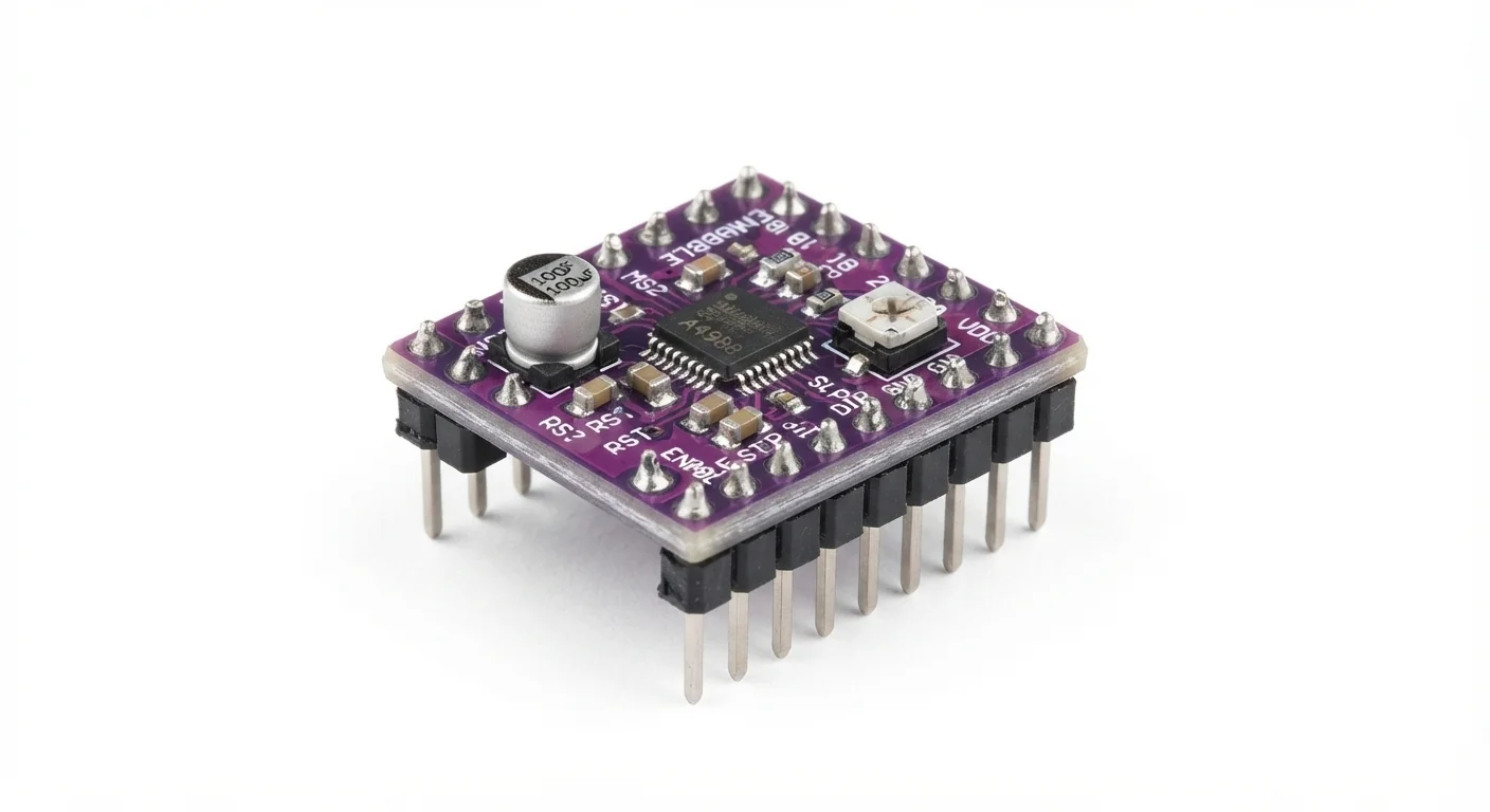
- Documentation and source review only. Not compiled or tested on hardware. The approved product-style illustration identifies a family, not a verified physical pin layout or manufacturer-authenticated board. Follow the logical diagram and documentation for your actual part.
Overview
A4988 turns STEP pulses and a DIR level into controlled currents in two windings. ESP32 sends commands; external supply and driver provide motor current. It is for bipolar steppers, not servos or the separate DC-motor example.
Purple board color does not prove DRV8825, revision, pin order or current-sense resistance. The approved image depicts A4988 family only; use the documented Pololu item 1182 reference or verify another carrier schematic. Never connect/disconnect the motor while powered.
Technical Specifications
Arduino library: Arduino-ESP32 3.3.2 built-in GPIO and timing; no extra library.
| Specification | Value | Why it matters |
|---|---|---|
| Mode | Full step; MS1/MS2/MS3 LOW | No universal angle per pulse. |
| Current limit | Imax ≤0.5 A and ≤motor rating | VREF = 8 × Imax × Rs; supply current is not coil current. |
| Reference calculation | Rs=0.068 ohm: 0.5 A → 0.272 V | Only for that verified revision, not another carrier preset. |
| STEP timing | 5 µs HIGH; about 10 ms LOW | Datasheet minimum HIGH/LOW is 1 µs; no acceleration profile. |
| Reference supply limits | VDD 3–5.5 V; VMOT 8–35 V | Worked VDD is 3.3 V and VMOT is 12 V; ESP32 uses separate USB power. |
| Control versus winding voltage | 3.3 V control with VDD at 3.3 V | Motor outputs and the 12 V supply never connect to ESP32 GPIO. Common ground does not mean joining positive rails. |
Pinout
- VDD Logic ESP32 3V3 Reference VDD, not VMOT.
- Logic and motor GND Reference ESP32 GND / supply negative Motor return directly to supply, not GPIO wiring.
- VMOT Power External regulated +12 V Never connect to ESP32.
- ≥47 µF / ≥25 V capacitor Bulk + VMOT; − motor GND Close to carrier; not a guarantee against all spikes.
- STEP Pulses GPIO25 + 10 kOhm to GND Hardware pull-down.
- DIR Direction GPIO26 + 10 kOhm to GND LOW for the example.
- /ENABLE Enable GPIO27 + 10 kOhm to 3V3 Active LOW; reset pull-up disables outputs.
- /RESET and /SLEEP Run Both joined to VDD (3.3 V) Actual pin labels, not artwork geometry.
- MS1, MS2, MS3 Full step GND All selection inputs LOW.
- 1A / 1B Winding Motor coil A pair Identify continuity with all power removed.
- 2A / 2B Winding Motor coil B pair Never connect while powered.
Wiring Diagram
VDD3.3 V; VMOT12 V with local capacitor; common GND. STEP25, DIR26, /ENABLE27. RESET/SLEEP HIGH, MS1–3 LOW; separate winding pairs to 1A/B and 2A/B.
| Component terminal | ESP32 / circuit connection | Purpose and qualification |
|---|---|---|
| VDD | ESP32 3V3 | Reference VDD, not VMOT. |
| Logic and motor GND | ESP32 GND / supply negative | Motor return directly to supply, not GPIO wiring. |
| VMOT | External regulated +12 V | Never connect to ESP32. |
| ≥47 µF / ≥25 V capacitor | + VMOT; − motor GND | Close to carrier; not a guarantee against all spikes. |
| STEP | GPIO25 + 10 kOhm to GND | Hardware pull-down. |
| DIR | GPIO26 + 10 kOhm to GND | LOW for the example. |
| /ENABLE | GPIO27 + 10 kOhm to 3V3 | Active LOW; reset pull-up disables outputs. |
| /RESET and /SLEEP | Both joined to VDD (3.3 V) | Actual pin labels, not artwork geometry. |
| MS1, MS2, MS3 | GND | All selection inputs LOW. |
| 1A / 1B | Motor coil A pair | Identify continuity with all power removed. |
| 2A / 2B | Motor coil B pair | Never connect while powered. |
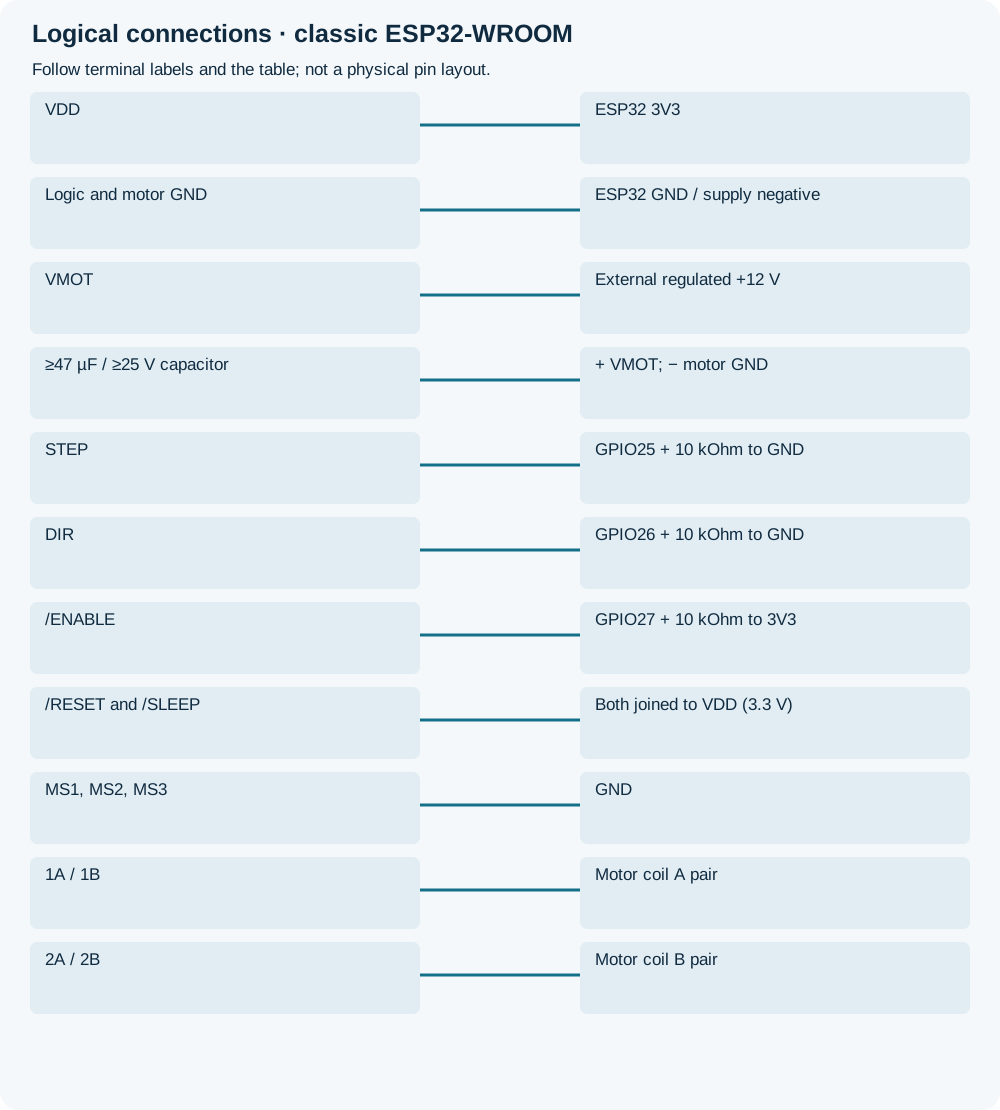
Open wiring diagram at full size (new tab)
-
1
Unpowered, identify carrier labels, Rs and motor coil pairs. Use manufacturer VREF procedure to set Imax ≤0.5 A and ≤motor rating. Rs=0.068 ohm gives 0.272 V for 0.5 A; do not copy to another Rs.
-
2
Adjust VREF with the motor disconnected using the manufacturer procedure, avoiding shorts/unintended outputs. Full-step coil current is about 70% of Imax; supply current is not a substitute. Remove power before attaching motor.
-
3
Install capacitor near VMOT, wire grounds/supplies/control pull resistors. Upload with motor power off. Keep shaft clear and unloaded.
-
4
Power the documented setup, send g at 115200 baud. The bounded pulse burst finishes disabled. Disconnect both supplies before wiring changes.
Wiring and matching Arduino code
Commanded full-step pulse burst
VDD3.3 V; VMOT12 V with local capacitor; common GND. STEP25, DIR26, /ENABLE27. RESET/SLEEP HIGH, MS1–3 LOW; separate winding pairs to 1A/B and 2A/B.
a4988_stepper_driver.ino
#include <Arduino.h>
constexpr uint8_t STEP_PIN = 25;
constexpr uint8_t DIR_PIN = 26;
constexpr uint8_t ENABLE_PIN = 27; // active LOW
void setup() {
  Serial.begin(115200);
  pinMode(ENABLE_PIN, OUTPUT);
  digitalWrite(ENABLE_PIN, HIGH);
  pinMode(STEP_PIN, OUTPUT);
  pinMode(DIR_PIN, OUTPUT);
  digitalWrite(STEP_PIN, LOW);
  digitalWrite(DIR_PIN, LOW);
  Serial.println("Set current limit first. Send g for 100 full-step pulses.");
}
void loop() {
  if (Serial.available() == 0) return;
  if (Serial.read() != 'g') return;
  digitalWrite(ENABLE_PIN, LOW);
  delay(2);
  for (uint16_t n = 0; n < 100; ++n) {
    digitalWrite(STEP_PIN, HIGH);
    delayMicroseconds(5);
    digitalWrite(STEP_PIN, LOW);
    delay(10);
  }
  digitalWrite(ENABLE_PIN, HIGH);
  Serial.println("100 pulses sent; outputs disabled. Movement is not sensed.");
}
Hardware /ENABLE pull-up provides reset bias. About one-second burst intentionally blocks other work: first bench test, not motion-control scheduler. Disabled motor has no holding torque; no gravity-loaded axis. Current limit is hardware setup, not code.
Expected Output
Unloaded motor should move during the burst, then lose holding torque. 100 commands do not prove 100 steps or a specific angle. If it vibrates, stop and check pairs/current setup rather than increasing current blindly.
How it works
A rising STEP edge advances the translator; DIR chooses direction and /ENABLE gates outputs. RESET/SLEEP stay HIGH. A chopper driver can use supply voltage above motor winding nominal voltage only with correct current limiting.
Imax = VREF/(8×Rs); verify real Rs, since reference revisions differ. Thermal limits, cooling and wiring matter. Chip protection does not establish safe operation of an unknown carrier at headline maximum current.
Troubleshooting
| Problem | Possible cause | Solution |
|---|---|---|
| Vibration without rotation | Mixed winding pairs, unsuitable motor or insufficient torque. | Power off, verify coils/rating and start unloaded at low rate. |
| No movement | Disabled output, RESET/SLEEP LOW or missing supply. | Trace the table and command; printed count is not movement feedback. |
| Excessive heat/cutout | Current too high or cooling inadequate. | Remove power and review current/thermal limits; do not raise VREF to fix wiring. |
| Failure after rewiring | Hot-plugged motor or voltage spike. | No powered rewiring; use local capacitor and short supply wiring. |
Where you use it
- Unloaded first stepper test
- Learning STEP/DIR and hardware current limiting
Continue learning
FAQ
No. Identify real IC/carrier from documentation, not color.
Only for a 200-step/revolution motor without missed steps; no universal angle claim.
Technical references
- Pololu A4988 carrier 1182 — Worked carrier labels, power, current limiting and thermal guidance.
- Allegro A4988 — STEP timing, current-limit equation and mode/logic requirements.
- Arduino-ESP32 3.3.2 GPIO — Pinned GPIO output implementation.