
Before you start
- Board and software
- Low-voltage bench setup as specified below. ESP32 is optional for passive exercises. Coded examples require classic ESP32-WROOM-32/32E DevKit, unused exposed pins, Arduino IDE 2.x and Arduino-ESP32 3.3.2 (review baseline, not a latest-release claim). Other families need their own pin map.
- Supported hardware
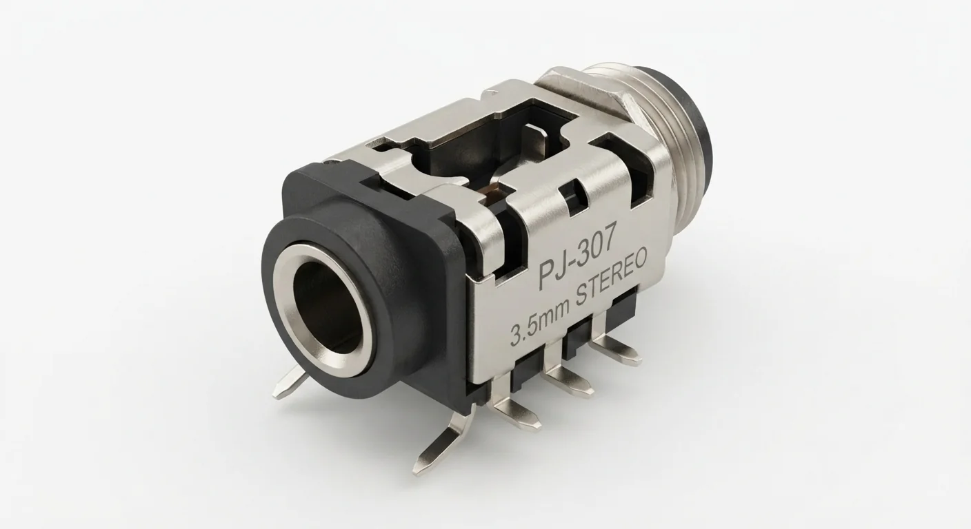
- Approved PJ-307-labelled 3.5 mm stereo jack illustration; exact drawing and switched contacts unverified. Worked contact terminology: known three-contact TRS jack, such as Same Sky SJ1-3523NG, not an identification of artwork.
- Prerequisites and parts
- Known TRS plug/breakout, actual jack drawing and continuity meter. Disconnect audio sources, amplifiers and ESP32. A TRRS headset is a different contact arrangement.
- Libraries
- No firmware or library required for this exercise. Arduino-ESP32 3.3.2 is the site review baseline, not a dependency of this passive setup.
- Expected result
- Each assigned jack terminal connects to the intended tip, ring or sleeve of an inserted unpowered TRS plug.
- Verification status
- Documentation and source review only. Not compiled or tested on hardware. The approved product-style illustration identifies a family, not a verified physical pin layout or manufacturer-authenticated board. Follow the logical diagram and documentation for your actual part.
Overview
A stereo TRS plug has tip, ring and sleeve separated by insulating rings. Conventional unbalanced stereo uses tip for left, ring for right and sleeve for return. That signal convention is not the mechanical solder-pin order.
Some jacks add switched contacts that change when a plug enters. Map them with the actual drawing and continuity test; leave unneeded switches isolated. The illustration label cannot establish a numbered footprint. TRRS headset microphone standards are outside this three-contact exercise.
Technical Specifications
Arduino library: No firmware or library required for this exercise
| Specification | Value | Why it matters |
|---|---|---|
| Contact system | 3.5 mm TRS | Three plug contacts; not TRRS. |
| Terminal numbers | From actual jack drawing | No universal footprint or switch order assumed. |
Pinout
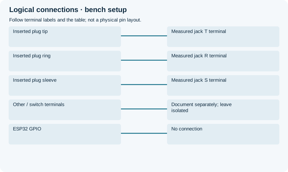
- Inserted plug tip Connection Measured jack T terminal Conventional left audio contact.
- Inserted plug ring Connection Measured jack R terminal Conventional right audio contact.
- Inserted plug sleeve Connection Measured jack S terminal Conventional return contact.
- Other / switch terminals Connection Document separately; leave isolated No inferred mechanical pin numbers.
- ESP32 GPIO Connection No connection This is an unpowered mapping exercise.
Wiring Diagram
Map plug tip/ring/sleeve to actual jack terminals using continuity, not drawing position.
| Component terminal | ESP32 / circuit connection | Purpose and qualification |
|---|---|---|
| Inserted plug tip | Measured jack T terminal | Conventional left audio contact. |
| Inserted plug ring | Measured jack R terminal | Conventional right audio contact. |
| Inserted plug sleeve | Measured jack S terminal | Conventional return contact. |
| Other / switch terminals | Document separately; leave isolated | No inferred mechanical pin numbers. |
| ESP32 GPIO | No connection | This is an unpowered mapping exercise. |
Open wiring diagram at full size (new tab)
-
1
Remove all power and audio sources.
-
2
Insert a known TRS test plug; measure and label each contact.
-
3
Repeat insertion/removal for switch identification and save the actual pin map.
Expected Output
With the plug inserted, label measured contacts T/R/S and record any switches separately. Continuity identifies connections, not audio impedance, gain or noise.
How it works
The jack spring contacts touch the corresponding plug surfaces. Use an unpowered test plug with accessible labelled conductors; test insertion/removal if switches exist. Do not join left and right amplifier outputs to make mono.
Troubleshooting
| Problem | Possible cause | Solution |
|---|---|---|
| More than three terminals | Jack includes switches or shell contacts. | Consult drawing and map with plug inserted/removed. |
| Hum or one channel missing | Return/contact mapping wrong or damaged jack. | Check unpowered TRS continuity before reconnecting audio. |
| Headset contacts differ | TRRS used instead of TRS. | Use the matching connector and headset standard; do not guess microphone pin. |
Where you use it
- Preparing a documented audio connector pin map
- Checking broken connector contacts before audio-circuit design
FAQ
No. Use actual drawing and continuity.
Not directly; it requires a suitable biased and protected input circuit.
Technical references
- Same Sky SJ1-352XNG drawing — A specific three-contact reference; not a PJ-307 footprint claim.