
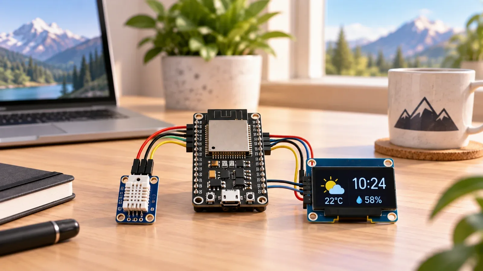
Build Your OLED Weather Clock
The Story
ESP32 OLED Weather Clock turns the ESP32 into a small desk display that combines network time with local room conditions.
The useful lesson is how several layers work together: Wi-Fi gets time from NTP, the timezone settings turn that into a local clock, the BME280 measures the environment, and the SSD1306 turns those values into something easy to read.
Explain Like I'm 12
Think of the ESP32 as a tiny clock brain. Wi-Fi lets it ask the internet for the current time, the timezone setting tells it what that time should look like where you live, the BME280 checks the room, and the OLED is the little screen that shows the result.
Safety Standards
- Unplug USB before changing jumper wires. Recheck 3.3 V and GND before reconnecting power.
- Keep the OLED and BME280 on the ESP32 I2C pins shown in the wiring table, or update the Wire.begin pins to match your board.
- Breadboards are for supervised, low-voltage prototypes. Move any permanent clock build into an insulated enclosure with strain relief for the USB cable.
What You Will Build
A Wi-Fi-synced ESP32 OLED clock that shows local time, temperature, humidity, and optional pressure on a compact SSD1306 display, with Serial Monitor diagnostics for Wi-Fi, NTP, OLED, and BME280 checks.
Learning Objectives
- Wire an SSD1306 OLED and BME280 sensor on the ESP32 I2C pins.
- Match SDA and SCL wiring to Wire.begin(21, 22) in the sketch.
- Connect ESP32 Wi-Fi and sync time from NTP.
- Configure UTC offset and daylight saving offset for local clock display.
- Read BME280 temperature, humidity, and pressure and format them for a 128x64 OLED.
Components List
- ESP32 DevKit boardMain controller with Wi-Fi
- BME280 environmental sensorMeasures temperature, humidity, and pressure
- SSD1306 OLED displayShows clock and weather readings
- Breadboard and jumper wiresPrototype the shared I2C bus
- USB data cableProgramming and testing
Bill of Materials
| Part | Qty | Estimated Cost | Notes |
|---|---|---|---|
| ESP32 DevKit | 1 | $6-$10 | USB board with Wi-Fi |
| BME280 sensor module | 1 | $3-$10 | Use BME280 for humidity; BMP280 does not measure humidity |
| SSD1306 OLED display | 1 | $3-$12 | Most I2C modules use address 0x3C; some use 0x3D |
| Breadboard and wires | 1 set | $3-$5 | Short I2C jumpers make debugging easier |
Wiring
Connect the SSD1306 OLED and BME280 to the same ESP32 I2C bus, then verify Wi-Fi and NTP before trusting the displayed time.
-
1
Unplug USB before placing the OLED or BME280 on the breadboard.
-
2
Connect OLED VCC to 3.3 V and OLED GND to ESP32 GND.
-
3
Connect OLED SDA to GPIO21 and OLED SCL to GPIO22.
-
4
Connect BME280 VIN or VCC to 3.3 V and BME280 GND to ESP32 GND.
-
5
Connect BME280 SDA to GPIO21 and BME280 SCL to GPIO22 so it shares the I2C bus with the OLED.
-
6
Reconnect USB, upload the sketch, and use Serial Monitor to confirm Wi-Fi, NTP, and BME280 startup messages.
GPIO Mapping
| Signal | ESP32 Pin | Direction | Notes |
|---|---|---|---|
| OLED SDA | GPIO21 | I2C data | Match Wire.begin(21, 22); some ESP32 boards expose different default SDA pins |
| OLED SCL | GPIO22 | I2C clock | Match Wire.begin(21, 22); keep jumpers short for reliable I2C |
| BME280 SDA | GPIO21 | I2C data | Shares the same bus as the OLED when the addresses do not conflict |
| BME280 SCL | GPIO22 | I2C clock | Most BME280 boards use address 0x76 or 0x77 |
| Wi-Fi and NTP | Internal radio | Network | NTP supplies UTC time; your offset controls the local display |
| Serial Monitor | USB | Debug | 115200 baud |
Circuit Explanation
The OLED and BME280 both use I2C, so they share SDA on GPIO21 and SCL on GPIO22 while keeping separate device addresses. The SSD1306 display is usually at 0x3C, while many BME280 boards use 0x76 or 0x77. Those addresses let the ESP32 talk to both modules on the same two signal wires.
Engineering Explanation
A reliable weather clock is built in layers. First initialize I2C, then confirm the OLED address, connect Wi-Fi, sync NTP time, apply the correct timezone offset, check the BME280 address, and only then draw the clock and weather values. Testing in that order makes a blank display or wrong time much easier to troubleshoot.
Code
Copy into Arduino IDE. Install any libraries noted in the component guides first.
#include <WiFi.h>
#include <Wire.h>
#include <Adafruit_GFX.h>
#include <Adafruit_SSD1306.h>
#include <Adafruit_BME280.h>
#include <time.h>

#define I2C_SDA 21
#define I2C_SCL 22
#define OLED_ADDRESS 0x3C
#define SCREEN_WIDTH 128
#define SCREEN_HEIGHT 64

const char* ssid = "YOUR_WIFI";
const char* password = "YOUR_PASSWORD";

// NTP supplies UTC. Set these values for your local time zone.
const long GMT_OFFSET_SEC = 0;
const int DAYLIGHT_OFFSET_SEC = 0;

Adafruit_SSD1306 display(SCREEN_WIDTH, SCREEN_HEIGHT, &Wire, -1);
Adafruit_BME280 bme;
bool bmeReady = false;

void showMessage(const char* line1, const char* line2) {
  display.clearDisplay();
  display.setTextSize(1);
  display.setTextColor(SSD1306_WHITE);
  display.setCursor(0, 0);
  display.println(line1);
  display.println(line2);
  display.display();
}

bool beginBME280() {
  if (bme.begin(0x76)) return true;
  if (bme.begin(0x77)) return true;
  return false;
}

void setup() {
  Serial.begin(115200);
  Wire.begin(I2C_SDA, I2C_SCL);

  if (!display.begin(SSD1306_SWITCHCAPVCC, OLED_ADDRESS)) {
    Serial.println("SSD1306 not found. Check address, power, SDA, and SCL.");
    while (true) delay(1000);
  }

  showMessage("OLED Weather Clock", "Connecting WiFi...");

  WiFi.begin(ssid, password);
  while (WiFi.status() != WL_CONNECTED) {
    delay(300);
    Serial.print(".");
  }
  Serial.println();
  Serial.print("WiFi connected: ");
  Serial.println(WiFi.localIP());

  configTime(GMT_OFFSET_SEC, DAYLIGHT_OFFSET_SEC, "pool.ntp.org", "time.nist.gov");

  bmeReady = beginBME280();
  Serial.println(bmeReady ? "BME280 ready" : "BME280 not found");
  showMessage("Clock ready", bmeReady ? "BME280 ready" : "Check BME280");
  delay(1200);
}

void loop() {
  struct tm timeinfo;
  if (!getLocalTime(&timeinfo)) {
    Serial.println("Waiting for NTP time...");
    showMessage("NTP sync", "Waiting...");
    delay(1000);
    return;
  }

  char timeText[6];
  char dateText[18];
  strftime(timeText, sizeof(timeText), "%H:%M", &timeinfo);
  strftime(dateText, sizeof(dateText), "%a %d %b", &timeinfo);

  display.clearDisplay();
  display.setTextColor(SSD1306_WHITE);
  display.setTextSize(2);
  display.setCursor(0, 0);
  display.println(timeText);

  display.setTextSize(1);
  display.setCursor(0, 22);
  display.println(dateText);

  if (bmeReady) {
    display.print("Temp: ");
    display.print(bme.readTemperature(), 1);
    display.println(" C");
    display.print("Hum:  ");
    display.print(bme.readHumidity(), 0);
    display.println(" %");
    display.print("Pres: ");
    display.print(bme.readPressure() / 100.0F, 0);
    display.println(" hPa");
  } else {
    display.println("BME280 not found");
    display.println("Clock only mode");
  }

  display.display();
  delay(2000);
}
Code Explanation
The sketch starts I2C with Wire.begin(21, 22), initializes the SSD1306 at 0x3C, connects to Wi-Fi, and starts NTP with configTime. In the loop, getLocalTime returns the current local time, strftime formats it for the screen, the BME280 readings are collected when the sensor is detected, and the OLED is refreshed every two seconds.
Expected Output
The OLED should show local HH:MM time, the date, temperature in Celsius, humidity percent, and pressure in hPa when a BME280 is connected. Serial Monitor should report Wi-Fi connection, BME280 status, and any NTP waiting messages.
Troubleshooting
- OLED stays blank Confirm 3.3 V, GND, SDA on GPIO21, SCL on GPIO22, and the OLED address. Try 0x3D if your module is not found at 0x3C.
- BME280 is not detected Check the shared I2C wiring and sensor address. Most BME280 modules answer at 0x76 or 0x77.
- Time is wrong NTP gives network time in UTC. Set GMT_OFFSET_SEC and DAYLIGHT_OFFSET_SEC for your location before judging the displayed time.
- NTP sync keeps waiting Verify SSID, password, router access, and that the ESP32 can reach pool.ntp.org from your network.
- OLED works alone but fails with the BME280 connected Make sure both modules share SDA and SCL cleanly, use short jumpers, and confirm the devices do not use the same I2C address.
Common Mistakes
- Leaving GMT_OFFSET_SEC at 0 and expecting local time in every country.
- Buying a BMP280 board and expecting humidity; use BME280 if humidity is required.
- Swapping SDA and SCL or using pins that do not match Wire.begin(21, 22).
- Assuming every OLED is address 0x3C; some modules use 0x3D.
- Powering an I2C module from 5 V when the board is not clearly 3.3 V safe.
Testing Checklist
- ESP32 appears on the correct port and accepts a basic upload.
- OLED VCC is on 3.3 V, GND is shared, SDA is GPIO21, and SCL is GPIO22.
- OLED address 0x3C is correct, or the code is changed to 0x3D for your module.
- BME280 is connected to the same SDA and SCL lines and is detected at 0x76 or 0x77.
- Serial Monitor prints the Wi-Fi IP address.
- The OLED shows local time after NTP sync.
- Temperature, humidity, and pressure update about every two seconds.
Upgrade Ideas
- Add a setup screen for timezone and 12-hour or 24-hour display.
- Show pressure trend arrows after storing recent BME280 readings.
- Alternate between clock, weather, and Wi-Fi status screens.
- Add deep sleep or dimming for a desk clock enclosure.
Real-World Applications
- Classroom weather clock trainer
- Desk clock with room conditions
- Environmental display prototype
- IoT portfolio project
- I2C debugging practice
Downloads
- ESP32 OLED Weather Clock Arduino sketchUse the code section as the downloadable source until file downloads are published.
- Wiring checklistMatch the GPIO table and wiring steps before powering the circuit.
- Troubleshooting worksheetRecord OLED address, BME280 address, Wi-Fi status, NTP status, and fixes.
FAQs
Why is the displayed time not my local time?
NTP supplies UTC time. Set GMT_OFFSET_SEC and DAYLIGHT_OFFSET_SEC for your location before using the clock as a local display.
Can I build the clock without a BME280?
Yes. The sketch will still show the NTP clock and a BME280 warning, but the complete weather clock needs a BME280 for temperature, humidity, and pressure.
Why does the OLED not respond?
Check OLED power, ground, SDA on GPIO21, SCL on GPIO22, and the display I2C address before replacing the screen.
Review, Testing, and References
Author: Abdul Mubeen and the ESP32 Engine editorial team. Last updated: 2026-06-29. Reviewed: wiring logic, Arduino code structure, beginner safety, and learning sequence.
Educational level: Beginner. Estimated completion time: 90-150 min. This project is for learning and prototyping; production or unattended hardware needs additional engineering review.
Project Complete!
You built an ESP32 OLED weather clock that combines Wi-Fi time, local timezone configuration, BME280 environmental readings, and a compact SSD1306 display.
- Wire SSD1306 and BME280 modules on the same I2C bus
- Sync ESP32 time with NTP over Wi-Fi
- Configure timezone offset for local clock display
- Show temperature, humidity, and pressure on an OLED