
Build Your IoT Weather Station
The Story
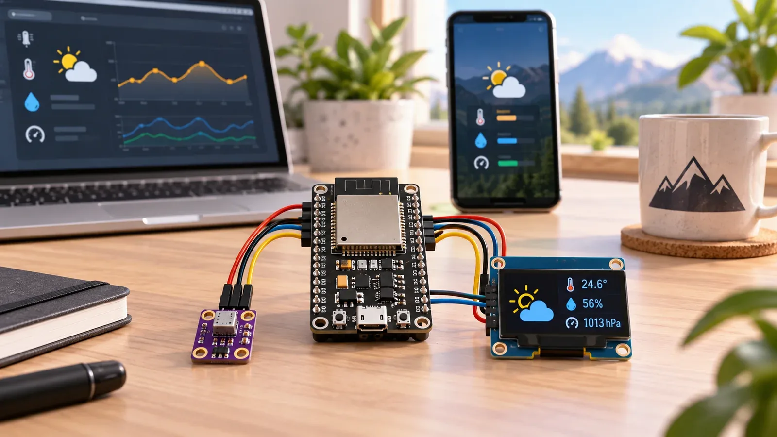
ESP32 IoT Weather Station turns the ESP32 into a local environmental monitor. The core build reads a BME280 over I2C using GPIO21 for SDA and GPIO22 for SCL, then prints temperature, humidity, and local pressure in Serial Monitor before you add any dashboard.
The important lesson is not only the finished weather station. You learn how to make sensor data trustworthy first: wire the bus, verify the address, place the sensor well, and understand what each reading actually means.
Explain Like I'm 12
Think of the ESP32 as the brain. The BME280 environmental sensor is how it notices the world. The Serial Monitor is how it reports the numbers. Once the readings are reliable, an optional OLED or dashboard can show the same data without changing the basic measurement idea.
Safety Standards
- Unplug USB before changing jumper wires. Recheck 3.3 V, GND, SDA, and SCL before reconnecting power.
- Use 3.3 V operation for the BME280 breakout unless that exact module documents safe 5 V input and level shifting.
- Keep I2C signal levels ESP32-safe and share ground between the ESP32 and any connected BME280 or OLED module.
- Protect outdoor sensors from rain and condensation while still allowing representative airflow.
What You Will Build
A working local ESP32 weather node that powers a BME280 breakout from 3.3 V, reads temperature, humidity, and pressure over I2C on GPIO21/GPIO22, prints clear Serial Monitor diagnostics, and can later be extended with an OLED, MQTT, logging, or a Wi-Fi dashboard.
Learning Objectives
- Wire a BME280 sensor over I2C using common Arduino-ESP32 GPIO21/GPIO22 defaults.
- Detect whether the BME280 responds at 0x76 or 0x77.
- Read temperature, humidity, and pressure and print clear labeled Serial Monitor values.
- Interpret local pressure in hPa without confusing it with sea-level adjusted weather reports.
- Identify placement-induced errors from heat, breath, sunlight, enclosures, and poor airflow.
- Share the I2C bus with an optional SSD1306 OLED later when addresses do not conflict.
- Extend reliable local sensor data into MQTT, logging, or a Wi-Fi dashboard after the core reading works.
Components List
- ESP32 DevKit boardMain controller with Wi-Fi
- BME280 sensor moduleTemperature, humidity, and pressure sensor
- SSD1306 OLED displayOptional local display for readings
- Breadboard and jumper wiresFor safe low-voltage prototyping
- USB data cableProgramming and bench power
Bill of Materials
| Part | Qty | Estimated Cost | Notes |
|---|---|---|---|
| ESP32 DevKit | 1 | $6-$10 | Use a USB-programmable board |
| BME280 module | 1 | $3-$8 | Prefer I2C breakout |
| SSD1306 OLED | 1 optional | $3-$6 | I2C 128x64 display |
| Breadboard and wires | 1 set | $3-$5 | Male-to-male jumpers |
Wiring
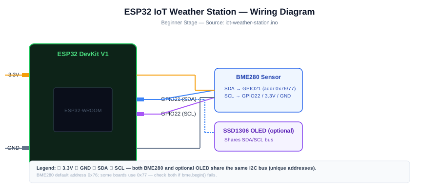
Wire the BME280 first: VCC to 3.3 V, GND to GND, SDA to GPIO21, and SCL to GPIO22. Verify temperature, humidity, pressure, and the detected 0x76 or 0x77 I2C address in Serial Monitor before adding an optional OLED, MQTT feed, or Wi-Fi dashboard.
-
1
Unplug USB before wiring the breadboard.
-
2
Connect the BME280 breakout VCC to 3.3 V unless that exact breakout documentation says another supply is safe.
-
3
Connect BME280 GND to ESP32 GND.
-
4
Connect BME280 SDA to GPIO21 and SCL to GPIO22, the common Arduino-ESP32 I2C defaults.
-
5
Reconnect USB, upload the core sketch, and open Serial Monitor at 115200 baud.
-
6
If you later add an OLED, connect its SDA and SCL to the same I2C bus, confirm its address, and keep signals ESP32-safe.
GPIO Mapping
| Signal | ESP32 Pin | Direction | Notes |
|---|---|---|---|
| BME280 VCC | 3.3 V | Power | Use 3.3 V unless the exact breakout documents another safe input. |
| BME280 GND | GND | Ground | Shared ground for the I2C sensor bus. |
| BME280 SDA | GPIO21 | I2C data | Common Arduino-ESP32 SDA default |
| BME280 SCL | GPIO22 | I2C clock | Common Arduino-ESP32 SCL default |
| OLED SDA | GPIO21 | I2C data | Optional display on shared I2C bus |
| OLED SCL | GPIO22 | I2C clock | Optional display on shared I2C bus |
Circuit Explanation
The BME280 uses I2C, so the ESP32 communicates over SDA and SCL. In this project, BME280 VCC connects to 3.3 V, GND connects to GND, SDA connects to GPIO21, and SCL connects to GPIO22. GPIO21 and GPIO22 are common Arduino-ESP32 defaults, but I2C pins are configurable in code. Most BME280 modules respond at 0x76 or 0x77. An optional SSD1306 OLED can share the same bus when its address, often 0x3C or sometimes 0x3D, does not conflict.
Engineering Explanation
Environmental readings are sensitive to placement. Heat from the ESP32, USB regulator, OLED, fingers, direct breath, direct sunlight, closed enclosures, and poor airflow can skew temperature and humidity. For meaningful room readings, place the BME280 away from heat-producing electronics, allow airflow, avoid touching it during measurement, and let readings stabilize. For outdoor use, protect the sensor from rain and condensation without sealing it away from representative airflow.
Code
Copy into Arduino IDE. Install any libraries noted in the component guides first.
#include <Wire.h>
#include <Adafruit_BME280.h>

Adafruit_BME280 bme;

bool beginBME280() {
  if (bme.begin(0x76)) {
    Serial.println("BME280 found at I2C address 0x76");
    return true;
  }

  if (bme.begin(0x77)) {
    Serial.println("BME280 found at I2C address 0x77");
    return true;
  }

  return false;
}

void setup() {
  Serial.begin(115200);
  delay(200);

  Serial.println("ESP32 BME280 weather station");
  if (!beginBME280()) {
    Serial.println("BME280 not found at 0x76 or 0x77.");
    Serial.println("Check 3.3 V, GND, SDA=GPIO21, SCL=GPIO22, and module address.");
    while (true) delay(100);
  }

  Serial.println("Reading temperature, humidity, and pressure every 2 seconds");
}

void loop() {
  float tempC = bme.readTemperature();
  float humidity = bme.readHumidity();
  float pressureHpa = bme.readPressure() / 100.0F;

  Serial.print("Temperature C: ");
  Serial.print(tempC, 1);
  Serial.print(" | Humidity %: ");
  Serial.print(humidity, 1);
  Serial.print(" | Pressure hPa: ");
  Serial.println(pressureHpa, 1);

  delay(2000);
}
Code Explanation
The sketch starts Serial Monitor at 115200 baud, tries BME280 address 0x76 first, then tries 0x77 if needed. After the sensor is found, it reads temperature, humidity, and pressure every two seconds and converts pressure from pascals to hPa for readable weather-station output.
Expected Output
Serial Monitor should show the detected BME280 address, then temperature in Celsius, humidity in percent, and local atmospheric pressure in hPa every two seconds. Warm air from your hand should change the temperature slowly, and breath near the sensor may raise humidity after a short delay.
Build Photos
- Breadboard overviewShow the ESP32, BME280 placement, USB connection, and 3.3 V/GND rails clearly.
- Close-up wiringCapture SDA on GPIO21, SCL on GPIO22, 3.3 V, and GND so beginners can compare their build.
- Working outputShow Serial Monitor with temperature, humidity, pressure hPa, and the detected BME280 address.
Troubleshooting
- BME280 not found Confirm SDA on GPIO21, SCL on GPIO22, shared GND, 3.3 V power, and loose breadboard rows. The sketch automatically tries 0x76 and 0x77, so scan the bus if both fail.
- Humidity is missing, NAN, or unrealistic Check that the module is really BME280, not BMP280. Also check wiring, library selection, power, and whether the sensor has been touched or exposed to condensation.
- Temperature reads too high Move the BME280 away from the ESP32, USB regulator, OLED, fingers, direct breath, direct sunlight, and closed enclosures. Let readings stabilize with airflow.
- Pressure differs from a weather app The sketch prints local absolute pressure in hPa. Weather services often show sea-level adjusted pressure, so altitude compensation is needed for direct comparison.
- OLED is not detected after adding it Confirm OLED SDA/SCL wiring, shared ground, module voltage compatibility, and address. SSD1306 OLED modules are often 0x3C and sometimes 0x3D.
- Readings jump or drift Improve airflow, avoid breathing on the sensor, secure loose wires, check USB power, and move the BME280 away from heat sources.
Common Mistakes
- Using a BMP280 board and expecting humidity readings; BMP280 measures temperature and pressure only.
- Assuming a missing or bad humidity value always proves BMP280; wiring, library, or module faults can also cause bad readings.
- Powering the sensor from 5 V when the breakout is not documented as 5 V tolerant or level shifted.
- Forgetting that common BME280 addresses are 0x76 and 0x77.
- Placing the sensor directly above the warm ESP32 module, USB regulator, or OLED.
Testing Checklist
- ESP32 appears on the correct port and accepts a basic blink upload.
- Ground is shared between every module that exchanges signals with the ESP32.
- Each GPIO in the code matches the wire connected on the breadboard.
- Serial Monitor prints startup text at 115200 baud.
- Startup text reports whether the BME280 was found at 0x76 or 0x77.
- Temperature, humidity, and pressure print every two seconds with clear labels.
- The BME280 readings change slowly when the air around the sensor changes.
- Optional OLED or dashboard work is added only after Serial Monitor readings are stable.
- The circuit still behaves correctly after power is removed and restored.
Upgrade Ideas
- Add optional SSD1306 OLED pages for current readings after the Serial Monitor version is stable.
- Publish readings to MQTT or a local web dashboard over Wi-Fi.
- Store pressure history and show rising or falling trend.
- Add deep sleep and proper weather shielding for outdoor battery logging.
Real-World Applications
- Classroom weather station
- Greenhouse monitoring
- Desk comfort monitor
- Pressure trend logger
- IoT dashboard sensor node
Downloads
- ESP32 IoT Weather Station Arduino sketchUse the code section as the downloadable source until file downloads are published.
- Wiring checklistMatch the GPIO table and wiring steps before powering the circuit.
- Troubleshooting worksheetRecord symptoms, Serial output, voltage checks, and fixes.
FAQs
Why does my BME280 environmental sensor reading look wrong?
Most wrong readings come from reversed power, loose breadboard rows, wrong SDA/SCL wiring, heat from nearby electronics, direct breath, or reading the sensor before it has settled.
Why is the BME280 not found on I2C?
Check SDA on GPIO21, SCL on GPIO22, 3.3 V power, ground, and loose wires. The sketch automatically tries both common BME280 addresses, 0x76 and 0x77.
Why do readings drift when the board is on the desk?
Heat from the ESP32 or nearby electronics can warm the air around the sensor. Move the BME280 away from the ESP32 module for steadier room readings.
Why does pressure differ from my weather app?
The sketch prints local absolute pressure in hPa. Weather apps often show pressure adjusted to sea level, so altitude compensation is needed for a direct comparison.
Is OLED or MQTT included in the core sketch?
No. The core sketch is Serial Monitor only. Add OLED, MQTT, logging, or a dashboard after the BME280 readings are reliable.
Review, Testing, and References
Author: Abdul Mubeen and the ESP32 Engine editorial team. Last updated: 2026-08-22. Reviewed: wiring logic, Arduino code structure, beginner safety, and learning sequence.
Educational level: Beginner. Estimated completion time: 60-90 min. This project is for learning and prototyping; production or unattended hardware needs additional engineering review.
Project Complete!
You built a reliable local ESP32 BME280 weather station and learned how to validate temperature, humidity, and pressure readings before adding displays, logging, or dashboards.
- Wire a BME280 environmental sensor on the ESP32 I2C bus.
- Detect BME280 modules at 0x76 or 0x77.
- Read temperature, humidity, and pressure in Serial Monitor.
- Recognize placement and airflow errors in environmental readings.
- Extend stable sensor data to an optional OLED, MQTT dashboard, or logger later.