
Before you start
- Board and software
- Classic ESP32-WROOM DevKit / ESP32 Dev Module, Arduino IDE 2 and Arduino-ESP32 3.3.2 review baseline, not a latest-release claim. Match GPIO labels, not header positions.
- Circuit and dependencies
- GPIO34 ADC1; 10 kΩ potentiometer between 3V3 and GND; no 5 V input. Raw-count introduction, not a position/voltage calibration.
- Before this lesson
- PWM Fundamentals
- Evidence limits
- Expected behavior describes the example, not a hardware test performed in this review. Contributor media, where present, is identified separately; no compilation, board upload or accuracy measurement is claimed.
Read a Dial with the ESP32 ADC
The Story
So far, most of your inputs have been digital. A button is pressed or released. A GPIO is HIGH or LOW. That kind of thinking is powerful, but the real world is rarely only two choices.
Room light changes gradually. A volume knob turns smoothly. Soil becomes wetter or drier by degrees. A battery voltage falls slowly. Mission 08 teaches the ESP32 to measure those in-between values.
Explain Like I'm 12
A digital input is like asking, 'Is the door open?' The answer is yes or no.
An analog input is like asking, 'How open is the door?' It might be closed, halfway open, almost open, or anywhere between.
The ESP32 cannot directly think in smooth voltages, so it uses an ADC. The ADC looks at the voltage and turns it into a number. Low voltage becomes a small number. Higher voltage becomes a bigger number.
Mission Goal
Read a potentiometer with the ESP32 ADC and understand how a changing voltage becomes a number from 0 to 4095.
Estimated Time
35-40 min
Difficulty
Beginner
Prerequisites
No prerequisites.
Skills You'll Learn
- Explain the difference between digital and analog signals
- Describe what the ESP32 ADC does
- Read a potentiometer with analogRead()
- Understand why ESP32 ADC values range from 0 to 4095
- Recognize simple analog noise and why readings may wiggle
Components Required
- ESP32 DevKit boardReads the analog voltage with its ADC
- 10 kOhm potentiometerActs like a turnable voltage divider
- BreadboardHolds the potentiometer and jumper wires
- Jumper wiresConnect 3.3 V, GND, and GPIO34
- USB data cableUpload code and watch Serial Monitor
Analog Values Are In-Between Values
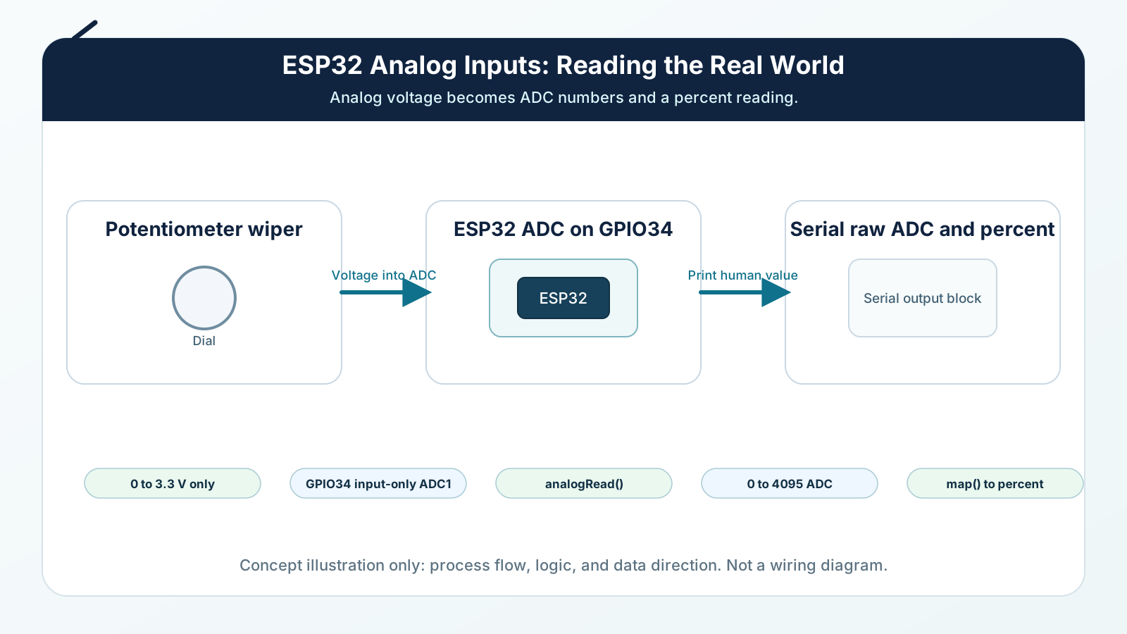
A potentiometer divides 3V3 and GND; its wiper supplies a changing voltage to GPIO34. With 12-bit resolution, analogRead() returns raw counts from 0 to 4095. Counts are neither volts nor a calibrated dial-position percentage. Observe the trend as you turn the dial; a flat reading near an endpoint can be saturation rather than a broken sensor.
Engineering Explanation
Review baseline: classic ESP32-WROOM DevKit and Arduino-ESP32 3.3.2, not a latest-release claim. GPIO34 is input-only ADC1 without internal pull resistors. This 3V3-powered potentiometer can approach the supply rail, but the classic ADC measurement range at 11 dB is approximately 150–3100 mV and can saturate near either end. Attenuation is not overvoltage protection: never apply 5 V or negative voltage. Raw full scale does not prove 3.3 V or a particular shaft position. Documentation reviewed; compilation and physical hardware testing have not been performed.
This quick build prints raw counts only. For ADC calibration and voltage-estimation details, see the Arduino-ESP32 ADC API under Technical references. On the classic ESP32, GPIO34 belongs to ADC1; ADC2 shares hardware with Wi-Fi. Short wiring and stable power help with noise but do not correct clipping.
Real-World Analogy
A light switch is digital: it is either off or on. A volume knob is analog: it can be quiet, medium, loud, or anywhere between.
A thermometer is another example. Temperature does not jump only between cold and hot. It moves gradually. Analog inputs let a microcontroller notice those gradual changes.
Think of the ADC like a ruler for voltage. The voltage is the real-world length. The ADC number is the ruler marking closest to where the voltage lands.
Wiring Diagram
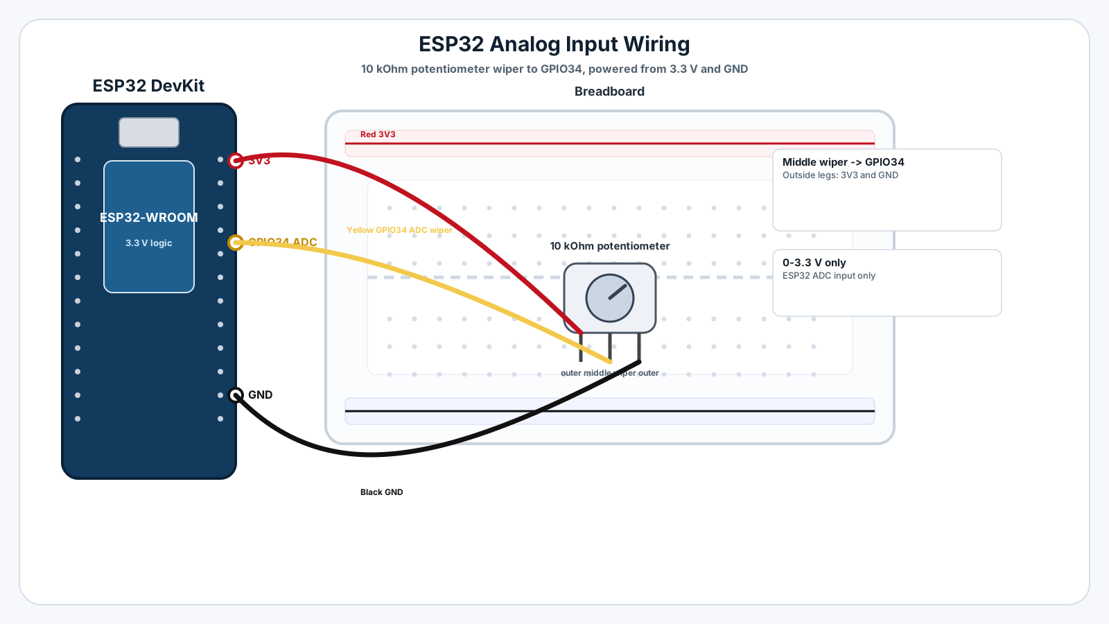
Follow these steps in order. Unplug USB before you change any wires.
-
1
Unplug the ESP32 USB cable before wiring.
-
2
Place the potentiometer on the breadboard.
-
3
Connect one outside potentiometer leg to ESP32 3.3 V.
-
4
Connect the other outside potentiometer leg to ESP32 GND.
-
5
Connect the middle potentiometer pin to ESP32 GPIO34.
-
6
Check that the middle pin goes to GPIO34, not directly to 3.3 V or GND.
-
7
Plug USB back in, upload the sketch, and open Serial Monitor at 115200 baud.
-
8
Turn the knob slowly and watch the values change.
GPIO Table
| Signal | ESP32 Pin | Mode | Notes |
|---|---|---|---|
| Potentiometer wiper | GPIO34 | Analog input | Reads the changing voltage from the middle pin. |
| Potentiometer high side | 3V3 | Power | Supply rail, not a guarantee of accurate ADC measurement up to 3.3 V. |
| Potentiometer low side | GND | Ground | Provides the low end of the dial. |
| Serial debug | USB | Serial | Shows raw ADC counts only. |
Arduino Code
Copy this into Arduino IDE, then click Upload.
#include <Arduino.h>
constexpr uint8_t POT_PIN = 34;
void setup() {
  Serial.begin(115200);
  analogReadResolution(12);
  analogSetPinAttenuation(POT_PIN, ADC_11db);
  Serial.println("Analog input ready: raw counts, not dial percent");
}
void loop() {
  const uint16_t raw = analogRead(POT_PIN);
  Serial.print("Raw ADC: ");
  Serial.println(raw);
  delay(200);
}GPIO34 reads the potentiometer wiper; outer terminals use 3V3 and GND.
Resolution and attenuation are explicit for the stated board/core.
Raw counts are not voltage or shaft-position percentage.
Line-by-line Explanation
- analogReadResolution(12) selects a 0–4095 result; analogSetPinAttenuation selects the wider classic-ESP32 measurement range.
- analogRead(POT_PIN) takes one raw sample. Serial prints the count without inventing a voltage or dial position.
- delay(200) limits output rate for this single-task observation sketch.
Recorded potentiometer readings
Explore the build photos and recorded results. Open any image to inspect the details.
About this recorded build
Contributor-supplied build photos and Arduino captures. These records are not an independent hardware retest. Some breadboard contacts are hidden; follow the documented pin connections.
The second supplied potentiometer set was byte-identical to the first. This gallery contains one copy of that recorded session.
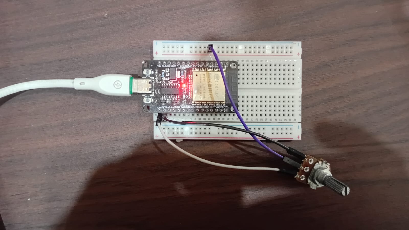
Supplied potentiometer build for GPIO34 raw ADC readings; the potentiometer resistance marking is not visible.
View full-size image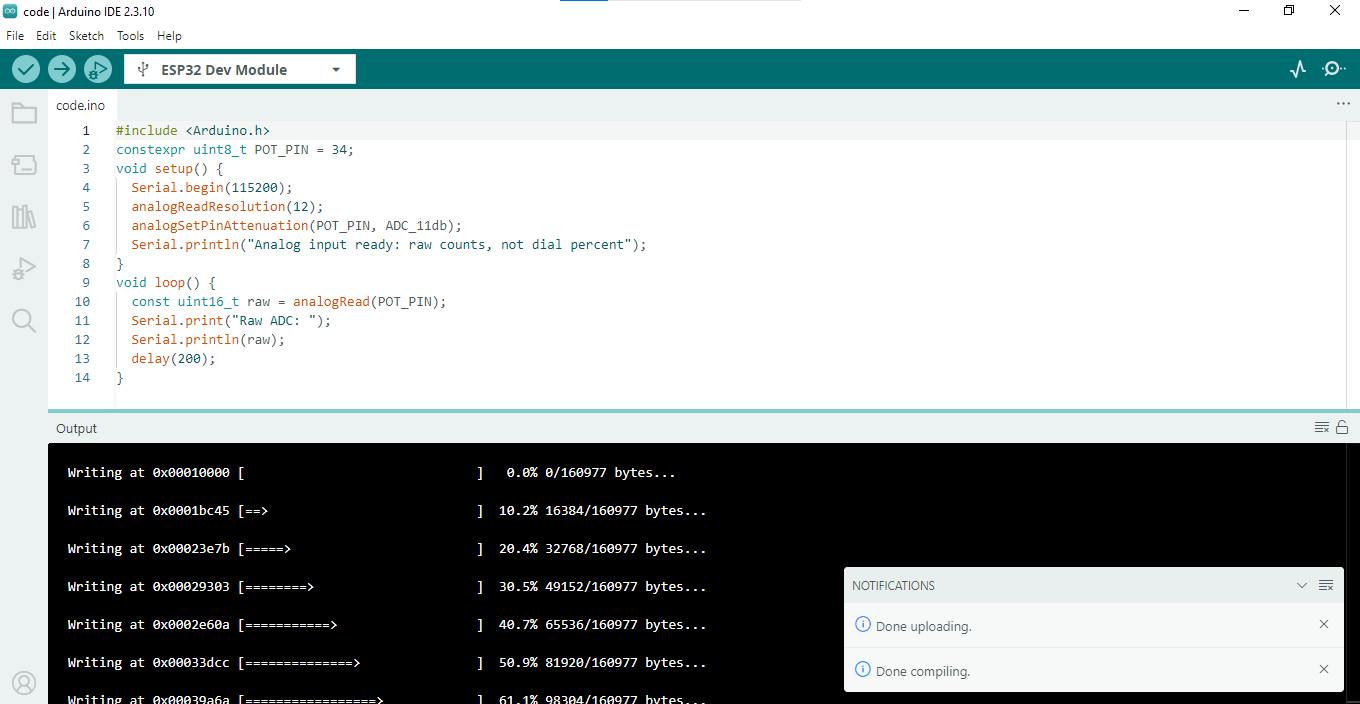
Supplied upload-completion capture for the raw ADC sketch used by this guide.
View full-size image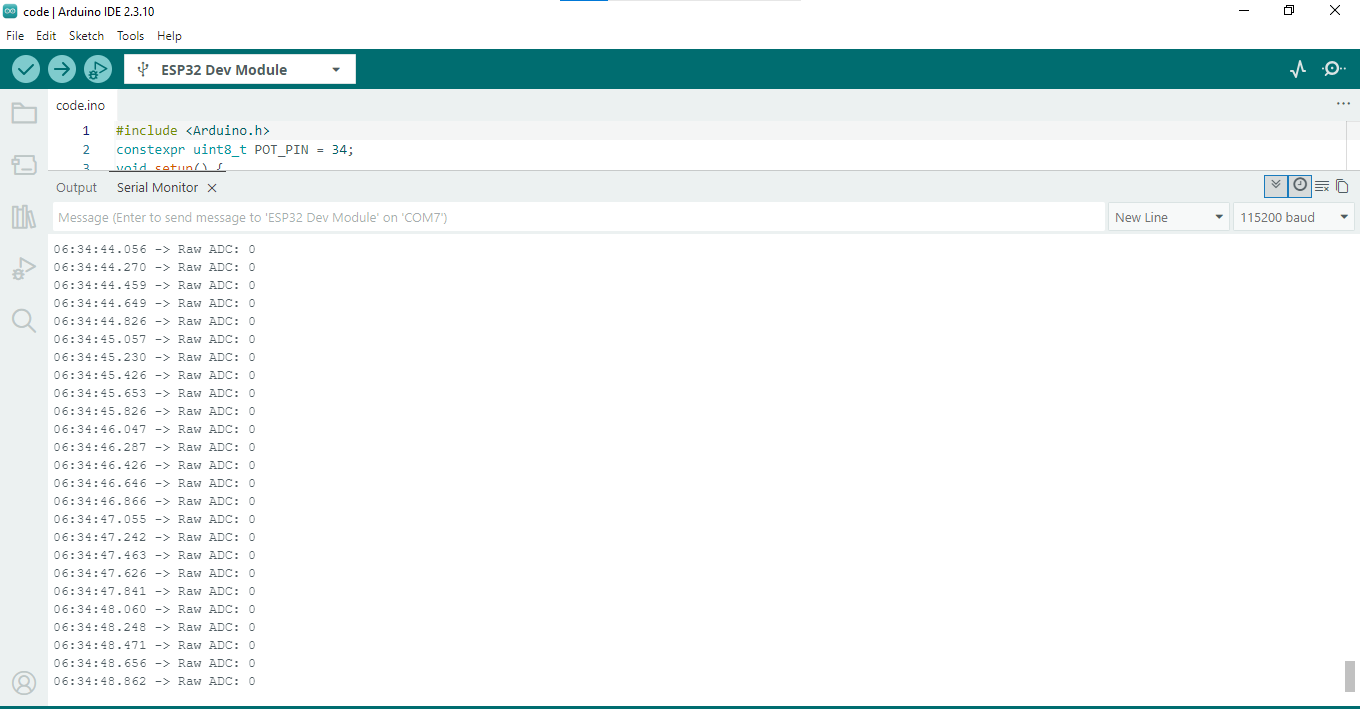
Dial at the supplied low-end position: recorded raw ADC count 0.
View full-size image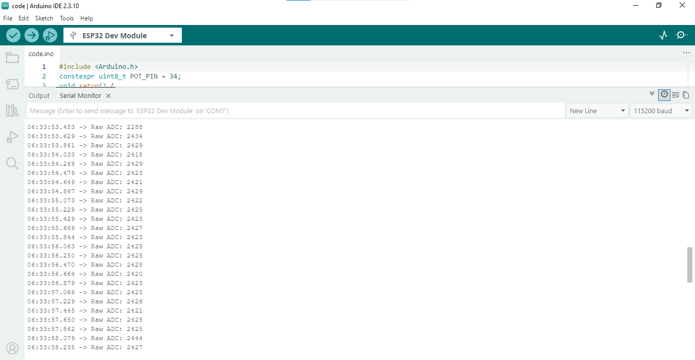
Approximate middle dial position: most displayed readings are around 2420–2444, with an initial 2288. This is not a calibrated 50% measurement.
View full-size image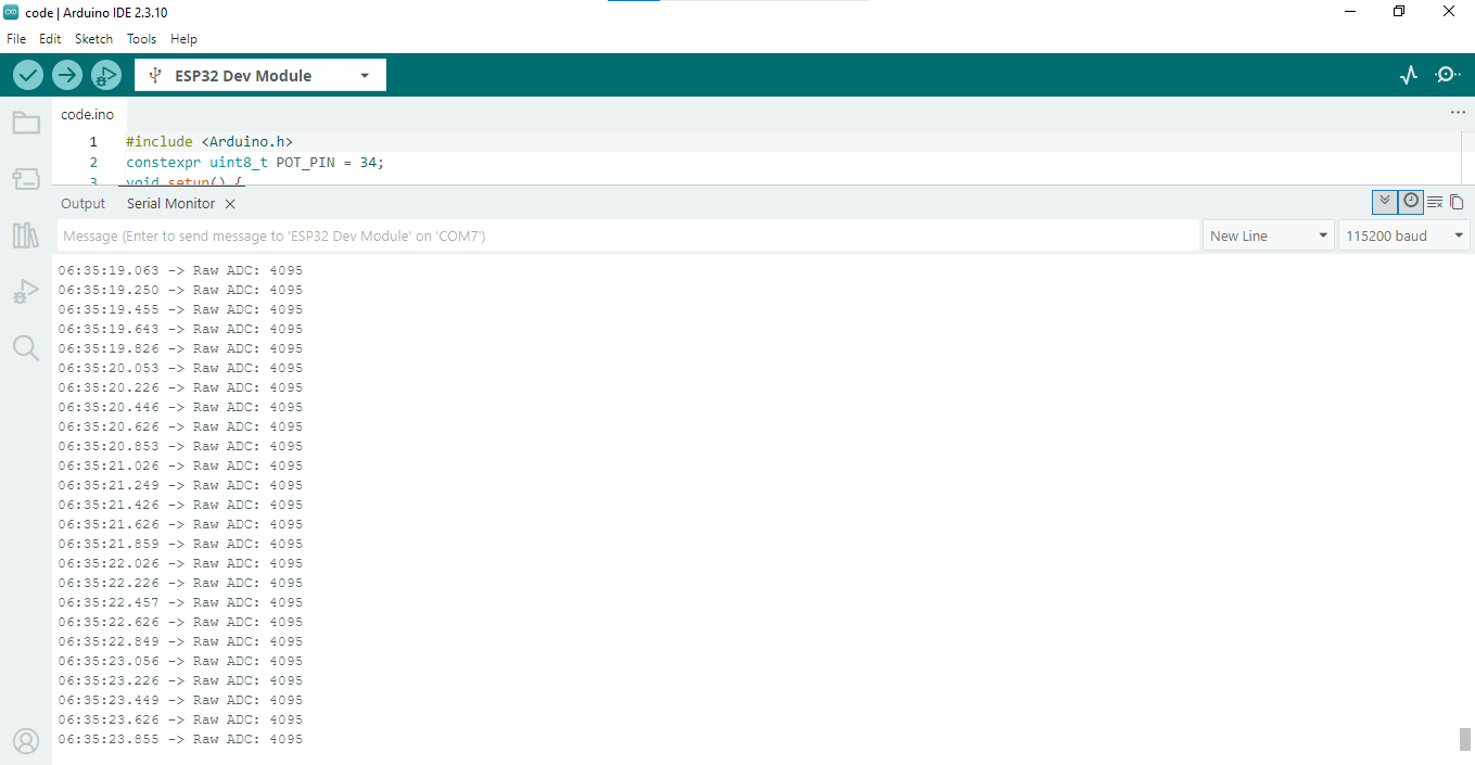
High-end dial position: recorded count 4095. ADC saturation does not establish an accurate voltage or shaft percentage.
View full-size imageCode and files
Expected Behaviour
At 115200 baud, expect the startup label followed by Raw ADC: <count>. The placeholder is not a measurement supplied by the tutorial. Turning the dial should change counts through much of its travel; noise and endpoint saturation are possible. Do not expect full scale to equal 3.3 V or half-scale to equal half the shaft travel.
Common Mistakes
Connecting the potentiometer to 5 V
Many Arduino examples use 5 V boards, but ESP32 GPIO pins are 3.3 V logic.
Using a non-ADC pin
Not every GPIO can read analog voltage.
Reading the wrong potentiometer leg
The outside legs are fixed ends; the middle leg is the changing wiper.
Expecting perfectly stable numbers
ADC readings naturally include small noise and variation.
Thinking 4095 means 4095 volts
The ADC value is a count, not a voltage unit.
Troubleshooting
Most ESP32 problems are wiring, power, library, or timing issues. Check these first.
The value stays at 0
Likely cause: GPIO34 may be connected to GND, or the middle pin may not be wired correctly.
Fix: Trace the potentiometer middle pin to GPIO34 and confirm one outer leg goes to 3.3 V.
The value stays near 4095
Likely cause: Wiper may be near a supply endpoint, the ADC may saturate, or the wire may be on an outer terminal.
Fix: Power off to trace the wiper connection. A 3V3-powered potentiometer can legitimately clip near its upper travel; do not increase voltage.
Values change backwards
Likely cause: The 3.3 V and GND outer legs are swapped.
Fix: This is safe if both are still 3.3 V and GND. Swap the outer wires if you want clockwise to increase.
Values jump around a lot
Likely cause: Loose breadboard wires, a damaged potentiometer, or noisy power can cause unstable readings.
Fix: Press wires firmly, try a different potentiometer, and keep jumper wires short.
Serial Monitor prints nothing
Likely cause: The board may not be connected, upload may have failed, or the baud rate may be wrong.
Fix: Upload again, choose the correct port, and set Serial Monitor to 115200 baud.
Engineer Tip
Always print the raw ADC value before turning it into a decision. If the raw number does not make sense, the project logic built on top of it will not make sense either.
Remember This Forever
Digital asks: is it ON?
Analog asks: how much?
The ADC is how the ESP32 turns a changing voltage into a number it can reason about.
Mini Challenge
No wrong answers — experiment and have fun!
- Record the raw count at several dial positions; identify noise or clipping without labelling counts as accurate position percentage.
- Take five readings, average them, and compare whether the number wiggles less.
- Swap the two outside potentiometer wires and observe how the direction changes.
- Explain how this analog dial could later control the PWM LED brightness from Mission 07.
FAQs
What is an analog signal?
An analog signal can change smoothly through many values instead of being only ON or OFF.
What is the difference between digital and analog input?
A digital input gives two answers, HIGH or LOW. An analog input gives a number that represents a voltage level.
What does ADC mean?
ADC means Analog-to-Digital Converter. It turns a voltage into a number the ESP32 can use.
Why does ESP32 analogRead() return 0 to 4095?
The ESP32 ADC commonly uses 12-bit readings. Twelve bits can represent 4096 possible values, numbered 0 through 4095.
What voltage should I use with ESP32 analog inputs?
Keep analog inputs within the ESP32's safe 3.3 V range. Do not feed 5 V into an ESP32 GPIO.
What is a potentiometer?
A potentiometer is a variable resistor with a rotating shaft. It can act like a dial that outputs a changing voltage.
Why does turning the potentiometer change the number smoothly?
The middle pin of the potentiometer slides between 0 V and 3.3 V, so the ADC sees many voltage levels between the two ends.
Why does my analog value wiggle when I am not touching the dial?
Small electrical noise, loose wiring, USB power noise, and ADC variation can make readings move by a few counts.
Is ADC noise a broken sensor?
Usually no. Small changes are normal. Real products often average or filter analog readings.
Can I use any ESP32 GPIO for analog input?
No. Only ADC-capable pins can read analog values. For beginner lessons, use a known ADC1 pin such as GPIO34.
Why use GPIO34 in this mission?
GPIO34 is an input-only ADC1 pin, which makes it a good safe choice for reading a potentiometer.
Can GPIO34 control an LED?
No. GPIO34 is input-only. Use it for reading, not output.
What happens if I connect the potentiometer backwards?
The numbers will move in the opposite direction. Low becomes high and high becomes low, but the ESP32 should still read safely if the ends are 3.3 V and GND.
Can analog input read negative voltage?
No. ESP32 GPIO pins should not receive negative voltage. Keep the signal between GND and 3.3 V.
Why do real products use analog inputs?
Many real-world conditions change gradually, such as light, pressure, position, moisture, battery voltage, and sound level.
Previous Mission
Next Mission
Continue Learning
Technical references
- Arduino-ESP32 3.3.2 ADC API — Raw counts, calibrated millivolts, attenuation and family-dependent ranges.