Before you start
- Example board
- Classic ESP32-WROOM-32/32E DevKit with a USB-to-UART bridge. ESP32-DevKitC V4 is the pinout reference; clone layouts can differ.
- Software route
- Arduino IDE 2 and esp32 by Espressif Systems. Arduino-ESP32 3.3.2 is this site’s API review baseline, not a latest-release claim.
- First result
- The linked setup guide prints ESP32 upload OK in Serial Monitor with no external circuit. Then follow the external-LED Blink guide. Documentation reviewed; no compilation or hardware test performed for this introduction.
Chip, module and development board
- Chip (SoC)
- The silicon device containing the processor, on-chip memory and peripherals. It runs firmware rather than a desktop operating system.
- Module
- A small board containing the chip and supporting parts. ESP32-WROOM-32E adds flash, a crystal and an antenna; module markings identify the particular product.
- Development board
- A larger board carrying a module, regulator, USB-to-UART bridge, buttons and headers. This is the convenient starting point for breadboard projects.
For example, an ESP32-WROOM module is soldered onto a DevKitC board. The board’s USB connector is not a GPIO input. Check the DevKit pinout and power reference before attaching wires.
A real ESP32 development board
Explore the build photos and recorded results. Open any image to inspect the details.
About this recorded build
These contributed photos show an ESP-32-marked USB-C development board. The exact module revision and board manufacturer are not established by the photographs; do not treat them as an official DevKitC V4 pin map.
Use the printed labels on your own board. The USB connector supplies the board and provides its upload connection; the GPIO signal-voltage limits remain separate.
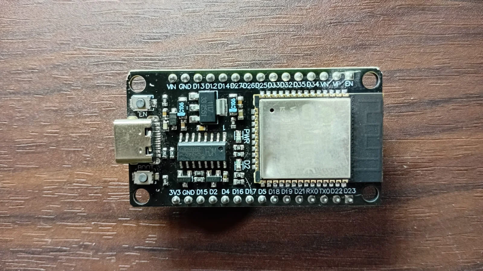
Front view of the supplied board. This is a hardware photograph, not the conceptual chip/module diagram.
View full-size image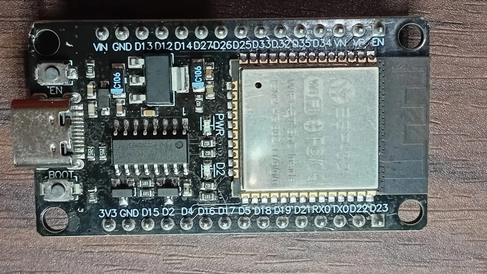
Pin-label close-up, rotated for readability. Read GPIO labels rather than counting header positions.
View full-size image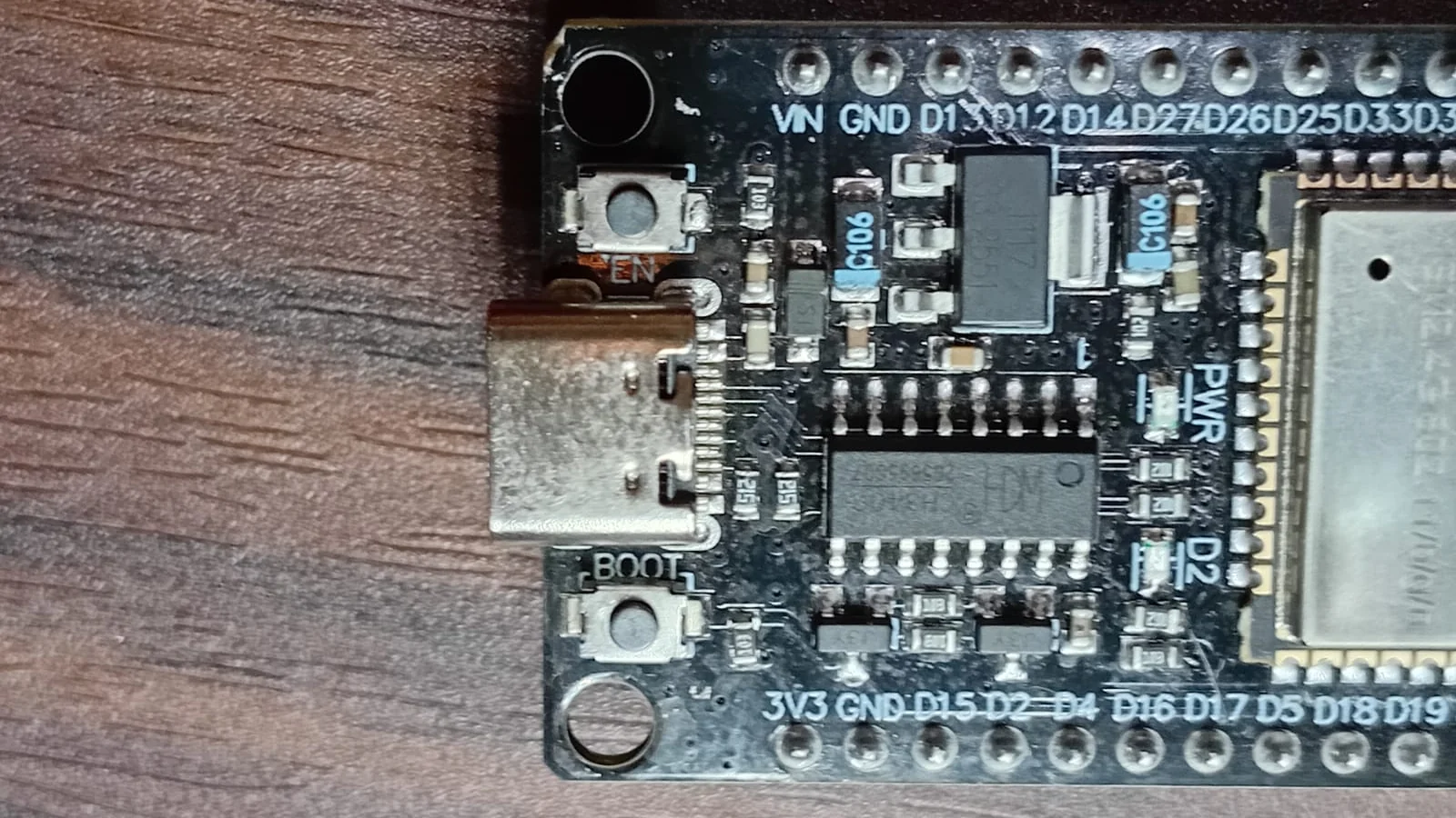
BOOT and EN labels on this particular board. Button placement and USB bridge designs vary.
View full-size imageStart here: your first working project
Use this existing beginner sequence. Finish each guide’s expected result before moving to the next; its wiring and software assumptions take precedence over generic board labels.
- Arduino IDE setup: install the board package, choose board and port, then verify a Serial-only upload. You need the DevKit, a USB data cable and a supported computer.
- Blink LED: add an external LED, a 220 Ω series resistor, breadboard and jumper wires. Learn how a digital output switches a small circuit. Do not assume an onboard LED is on GPIO2.
- Button input: add a tactile button and the pull resistor specified by that tutorial. Learn how a stable input controls the LED.
- DHT11 sensor: add the documented DHT11 and its required pull-up arrangement. Read temperature and humidity. This DHT11 tutorial retains its historical URL; it is not a DHT22 example.
- OLED display: add the specified 128×64 SSD1306 I2C module and display text using the documented SDA/SCL wiring.
These links lead to complete tutorials; there is no separate sketch to copy from this introduction. After the five steps, try a BME280 weather clock. An analog sensor or local web dashboard is a later extension, not an unfinished example here.
What the classic ESP32 example supports
The WROOM-32E example uses a dual-core Xtensa LX6 processor, with a rated maximum clock of 240 MHz. It supports 2.4 GHz Wi-Fi and Bluetooth Classic plus Bluetooth LE. These are properties of this classic hardware, not every chip with ESP32 in its name.
The classic chip has 520 KB of on-chip SRAM; firmware and wireless software use part of it, so this is not the available space for your variables. Flash stores the program, and its capacity depends on the module variant. PSRAM is extra memory present on some modules; do not assume a WROOM board includes it or that more flash fixes a RAM allocation problem.
Other families differ. ESP32-S2 has no Bluetooth. ESP32-S3 supports Bluetooth LE rather than Classic and uses LX7 processors. ESP32-C3 uses a RISC-V processor. S2/S3 chips have native USB capabilities; whether a board exposes a suitable connector and how it uploads depends on that board and firmware. The classic WROOM DevKit used here uploads through its USB-to-UART bridge, not native chip USB.
GPIO labels, peripheral counts and memory arrangements also vary. See classic ESP32 versus ESP32-S3 before carrying a pin map or Bluetooth example to another family.
Supply voltage, GPIO logic and analog measurements
- Board supply: use the documented USB power input for the first build. A regulator supplies the module’s operating rail. A USB or 5V supply label does not make the GPIO pins 5 V tolerant. DevKitC V4 power inputs are alternative methods, not inputs to connect together.
- Signals: the classic board uses 3.3 V GPIO logic. Do not connect a 5 V output directly to a GPIO. Verify each sensor’s supply requirement and signal levels separately; use suitable level conversion where required.
- ADC measurements: analog-capable pins convert voltage into a number. The usable measurement range depends on the chip and attenuation setting, and is not a universal 0–3.3 V range. A safe logic-level signal can still exceed the configured ADC measurement range. Raw counts are not automatically calibrated volts.
On classic ESP32, GPIO34–39 are input-only with no internal pull resistors, and not all are exposed on every module. Flash-connected and boot-strapping pins have other restrictions. ADC2 also shares hardware with Wi-Fi; prefer a documented ADC1 input for introductory analog builds.
Use the ADC guide for raw versus calibrated readings, attenuation and input limits rather than guessing a voltage conversion. Follow the actual board pin map before choosing a pin.
Power and deep sleep: board limits matter
Current changes with radio activity, CPU settings, attached loads and board design. Size the supply from the actual board and load documentation, including startup demand. A headline chip-current figure does not describe a complete DevKit. Motors, servos and relay coils need a suitable driver and rated supply; a GPIO is a control signal, not their power source.
Deep sleep powers down most of the classic chip while selected RTC functions can remain active. A timer or supported wake pin can restart the application; ordinary RAM state is not simply continued. The board’s regulator, USB bridge, LEDs and sensors can keep consuming power. Chip microamp specifications are not a promise for a USB DevKit or a battery runtime estimate. Follow the board-qualified deep-sleep guide when ready.
Compare named boards, not product families
| Feature | DevKitC V4 with WROOM-32E | Arduino Uno Rev3 | Raspberry Pi Pico W |
|---|---|---|---|
| GPIO logic | 3.3 V | 5 V | 3.3 V |
| Onboard wireless | 2.4 GHz Wi-Fi; Bluetooth Classic and LE | No onboard radio | 2.4 GHz Wi-Fi; Bluetooth Classic and LE with supported firmware |
| USB path | USB-to-UART bridge for upload/Serial | USB-to-serial interface | Native USB; available function depends on firmware |
| Choose for | The classic ESP32 examples on this site | Uno Rev3 lessons or compatible 5 V shields | RP2040/Pico-specific projects and software |
These are microcontroller boards, not general-purpose Linux computers. A Raspberry Pi single-board computer is a different product class. Do not select a board by clock speed alone or assume all Arduino-branded boards have Uno Rev3 specifications.
If the first upload or circuit does not work
No USB port
Try a known data cable and another port. Identify the actual USB bridge before installing its manufacturer’s driver. Holding BOOT does not turn a charge-only cable into a data cable.
Upload fails
Check board family and port first. Only use BOOT/EN recovery when appropriate to the documented classic UART board; native USB boards can need different settings. Use the setup guide’s recovery steps.
Repeated resets
Disconnect external loads with power off and retest the Serial-only sketch. Read reset messages, inspect wiring and verify the rated supply/cable. Do not add an arbitrary large capacitor as a universal repair.
Blank Serial Monitor
Match the sketch’s baud rate (115200 in the linked first test), choose the correct port and reset the board. USB CDC settings apply only to a supported native-USB workflow, not every classic DevKit.
Noisy analog readings
Check common reference, voltage limits, ADC-capable pin and attenuation. On classic ESP32, account for ADC2/Wi-Fi sharing. See the ADC guide before averaging or claiming voltage accuracy.
Next steps
Begin with the Serial-only upload in the Arduino IDE setup guide, then wire the external LED exactly as the Blink tutorial shows. Add the remaining beginner circuits one at a time; do not treat specifications from one ESP32 family as a pinout for another.
FAQ
MicroPython or CircuitPython is an option only with firmware built for the exact supported board. USB workflows differ. This beginner route uses Arduino-ESP32; the separate CircuitPython Feather ESP32-S3 guide identifies its supported board and installation path.
A local LED, button or sensor program can run without a network. Wi-Fi features need the network they were written for; a local-network project does not automatically require a cloud service.
Technical references
- Espressif ESP32-WROOM-32E/32UE datasheet — Classic module CPU, memory, radio and electrical specifications; module variants differ.
- Espressif ESP32-DevKitC V4 guide — Module, USB-to-UART, pin labels and mutually exclusive power inputs.
- Espressif ESP32-S2 datasheet — Family-specific USB and absence of Bluetooth.
- Espressif ESP32-S3 datasheet — LX7, Bluetooth LE and native USB capabilities.
- Espressif ESP32-C3 datasheet — RISC-V family distinction.
- Arduino-ESP32 3.3.2 source release — Pinned API review baseline for the linked Arduino learning route.
- Espressif ESP32 ADC oneshot documentation — Chip-specific analog pins, attenuation, calibration and ADC2/Wi-Fi sharing.
- Espressif ESP32 sleep modes — Power domains, wake sources and retained-state qualifications.
- Arduino Uno Rev3 hardware — Named Uno Rev3 comparison, not all Arduino boards.
- Raspberry Pi Pico-series documentation — Pico W GPIO, USB and supported wireless features.