
Before you start
- Hardware
- Classic ESP32-WROOM DevKit with GPIO33 exposed, USB data cable, 10 kΩ pull-up and optional normally open button for the displayed sketch. No S3/C3 pin compatibility assumed.
- Software
- Arduino-ESP32 3.3.2 review baseline; bundled esp_sleep and RTC IO APIs. ESP32 Dev Module board profile.
- Prerequisite
- Identify the exact board and use a known USB data cable. Arduino examples follow the Serial-only IDE first-upload guide; CircuitPython uses its separate firmware workflow.
- Expected result
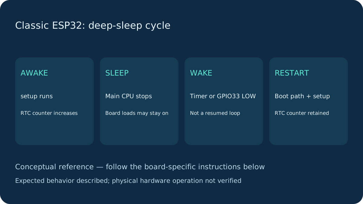
- Serial repeats setup after timer/button wake. An RTC counter increases across deep sleep; it is not persistent storage.
- Review limits
- Documentation review and automated content/browser checks only. Examples have not been compiled, uploaded or tested on physical hardware.
Wire the optional wake button
Connect GPIO33 through 10 kΩ to 3.3 V. Connect a normally open button between GPIO33 and GND; board ground is the reference. Released = HIGH, pressed = LOW. No 5 V signal is allowed. With only USB and no button/resistor, run a timer-only variant by removing the digitalRead/EXT0 branch; do not leave that input floating.
EXT0 is level-triggered, not an edge detector. If LOW is already present, the example skips EXT0 for that sleep and relies on the timer. This avoids immediate repeated wakes while a button is held.
Classic ESP32 wake sources and pins
The timer needs no external GPIO. EXT0 uses one RTC-capable GPIO at a chosen level. On classic ESP32 the RTC GPIO set is 0, 2, 4, 12–15, 25–27 and 32–39; that is not a beginner recommendation for every pin. Boot straps, input-only pins, missing internal pulls and board wiring still apply. GPIO33 avoids those particular classic-WROOM input-only/boot-strap restrictions.
EXT1 can combine RTC pins using its supported level logic; touch and ULP are separate wake mechanisms. Ordinary digital-GPIO wake in light sleep is not interchangeable with this deep-sleep EXT0 example. Early classic chip revisions have EXT0/touch/ULP combination restrictions. Consult the target-specific reference rather than moving this code to S3 unchanged.
Upload and observe the restart
Upload by USB, then open Serial at 115200. Release the button before sleep. Wait for the timer or briefly press the button after sleep begins. Wake runs the boot path and setup again; execution does not continue after esp_deep_sleep_start. The numeric cause comes from the pinned enum; TIMER and EXT0 distinguish the configured sources.
Wiring and matching Arduino code
Timer plus optional GPIO33 button
GPIO33 → 10 kΩ → 3.3 V; GPIO33 → normally open button → GND. USB powers the stated board.
deep-sleep-classic.ino
#include <Arduino.h>
#include <esp_sleep.h>
#include <driver/rtc_io.h>

constexpr gpio_num_t WAKE_PIN = GPIO_NUM_33;
RTC_DATA_ATTR uint32_t bootCount = 0;

void setup() {
  Serial.begin(115200);
  ++bootCount;
  const esp_sleep_wakeup_cause_t cause = esp_sleep_get_wakeup_cause();
  Serial.printf("RTC boot count: %lu, wake cause: %d\n",
                (unsigned long)bootCount, int(cause));
  // EXT0 leaves this pad in RTC mode. Restore digital GPIO before reading.
  rtc_gpio_deinit(WAKE_PIN);
  pinMode(int(WAKE_PIN), INPUT); // External 10 kOhm pull-up, not INPUT_PULLUP.
  delay(100); // Short, bounded awake window for Serial output.
  if (esp_sleep_enable_timer_wakeup(10ULL * 1000000ULL) != ESP_OK) {
    Serial.println("Timer setup failed; remain awake."); return;
  }
  if (digitalRead(int(WAKE_PIN)) == HIGH) {
    if (esp_sleep_enable_ext0_wakeup(WAKE_PIN, 0) != ESP_OK) {
      Serial.println("EXT0 setup failed; remain awake."); return;
    }
    Serial.println("Timer or button LOW can wake this classic ESP32.");
  } else {
    Serial.println("Button held LOW: timer only this cycle; release it.");
  }
  Serial.println("Entering deep sleep; setup runs again after wake.");
  Serial.flush();
  esp_deep_sleep_start();
}
void loop() { delay(100); } // Reached only if setup returned on an error.
Retained state is not a saved application
RTC_DATA_ATTR keeps this counter in RTC memory under the default power-domain configuration across deep sleep. Ordinary RAM/stack, network connections and application state do not resume. Power loss resets the counter; do not rely on it across an arbitrary reset, firmware upload or RTC power-down. For durable data use a separately designed flash/NVS strategy and consider write wear.
Radio work must finish before sleeping. A real sensor node wakes, initializes hardware, collects/sends data, then sleeps; this example intentionally does none of those network operations.
Measure the board, not just the chip specification
USB-UART bridges, power LEDs, regulators and attached modules may remain powered while the ESP32 sleeps. Datasheet chip sleep current is not a DevKit battery-current prediction. Measure the actual supply path and average the awake/sleep duty cycle; do not infer battery life from this counter demo. USB-powered tests verify behavior, not low-power performance.
If wake behavior differs
Immediate wake: check button polarity, a short to ground and whether the line remains LOW. No button wake: verify GPIO33, the 3.3 V pull-up and common ground; test HIGH/LOW while awake first. Serial disappears: some board USB implementations behave differently; this example is for a classic board with a UART bridge. Counter resets: check power interruption before assuming RTC retention is broken.
Next steps
Use the stated board and firmware assumptions. Compare actual observations with Expected result before extending the example.
Technical references
- ESP-IDF 5.5 sleep reference — Target-specific wake sources, RTC domains and pad restoration.
- Pinned sleep reference source — Version-pinned review evidence.
- 3.3.2 EXT0 example — RTC wake API usage.