
Before you start
- Hardware
- Comparison of a dual-core classic ESP32-WROOM DevKit and an ESP32-S3 development board whose module/flash/PSRAM/USB routing are documented.
- Software
- Datasheet comparison; site Arduino examples use the explicit 3.3.2 review baseline. Firmware/board-menu choices remain target-specific.
- Prerequisite
- Identify the exact board and use a known USB data cable. Arduino examples follow the Serial-only IDE first-upload guide; CircuitPython uses its separate firmware workflow.
- Expected result
- Choose a board by the required radio, USB workflow and usable pins rather than by its family name.
- Review limits
- Documentation review and automated content/browser checks only. Examples have not been compiled, uploaded or tested on physical hardware.
Compare chips before comparing boards
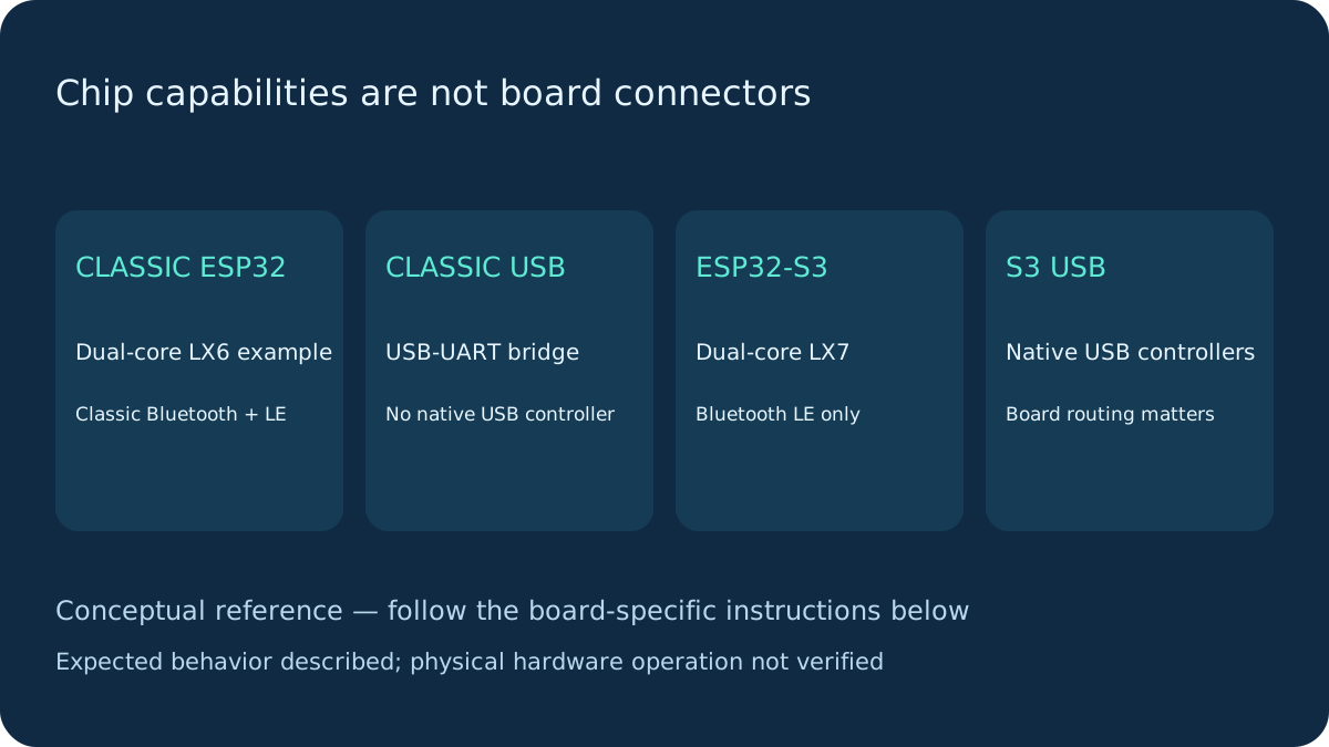
| Capability | Classic ESP32 (dual-core WROOM example) | ESP32-S3 |
|---|---|---|
| CPU | Xtensa LX6, two cores, up to 240 MHz for the stated dual-core part; classic series also contains single-core variants. | Xtensa LX7, two cores, up to 240 MHz, vector instructions. |
| Radio | 2.4 GHz Wi-Fi; Bluetooth 4.2 Classic BR/EDR and LE. | 2.4 GHz Wi-Fi; Bluetooth 5 LE, no Bluetooth Classic. |
| USB | No native USB peripheral; typical DevKit uses a separate USB-UART bridge. | Full-speed USB OTG and USB Serial/JTAG controllers. Board routing and firmware determine available USB functions. |
| GPIO | 34 programmable GPIOs at chip level; GPIO34–39 input-only. Six pins may serve external flash. | 45 programmable GPIOs at chip level (0–21 and 26–48); flash/PSRAM, strapping and USB can reserve pins. |
| Analog output | Two DAC channels on classic GPIO25/26. | No equivalent built-in DAC; PWM is not a DAC. |
Counts are chip capabilities, not the number of freely usable header pins. Both use 3.3 V GPIO logic; a board’s 5 V USB/VIN input does not make signal pins 5 V tolerant.
What the development board adds
A module can include flash, PSRAM and an antenna; a development board adds regulators, connectors, USB routing, buttons and sometimes a bridge or LED. An S3 chip feature is not proof that a particular USB socket connects to its native USB pins. Read the schematic and connector labels. Memory capacity and antenna type depend on the actual module.
Classic GPIO restrictions do not transfer numerically to S3. S3 native USB uses GPIO19/20, while its strapping pins include 0, 3, 45 and 46. GPIO46 remains a strapping pin; do not infer its restrictions from older pinout summaries. Flash/PSRAM package configurations reserve additional pins. Check the exact board schematic before selecting output, wake or analog pins.
Choose by the job
For existing classic-WROOM wiring, the classic DevKit is the shortest path through this site’s GPIO and sensor examples. A Bluetooth Classic/SPP requirement rules out S3. For supported native USB device workflows or vector-oriented processing, consider S3, then verify firmware support and memory. Vector instructions do not automatically turn an arbitrary sketch into a faster or validated AI application.
Both listed chips use 2.4 GHz Wi-Fi; neither comparison implies 5 GHz support. Bluetooth version labels do not prove that every optional feature is exposed by your selected Arduino library.
A small migration checklist
Identify the module, not just the seller’s board title. Select the matching IDE target and USB options. Re-map every GPIO against the schematic; check boot straps, flash/PSRAM and USB pins. Re-check ADC, sleep, LEDC, camera and Bluetooth APIs for the target/core. Keep a USB/bootloader recovery method. An S3 native USB cable may disappear/re-enumerate when firmware changes; a classic USB-UART bridge has a different role.
Use the specific CircuitPython Feather workflow linked below only on that supported board. Do not expect a CIRCUITPY drive from a generic classic WROOM board.
Next steps
Use the stated board and firmware assumptions. Compare actual observations with Expected result before extending the example.
Technical references
- ESP32 datasheet — LX6/radio/GPIO/DAC and series qualifications.
- ESP32-S3 datasheet — LX7, LE-only Bluetooth, USB controllers, GPIO/strap restrictions.
- ESP32-S3 capabilities at IDF 5.5 — Version-pinned valid GPIO/output masks; GPIO46 is not marked input-only in this baseline.