
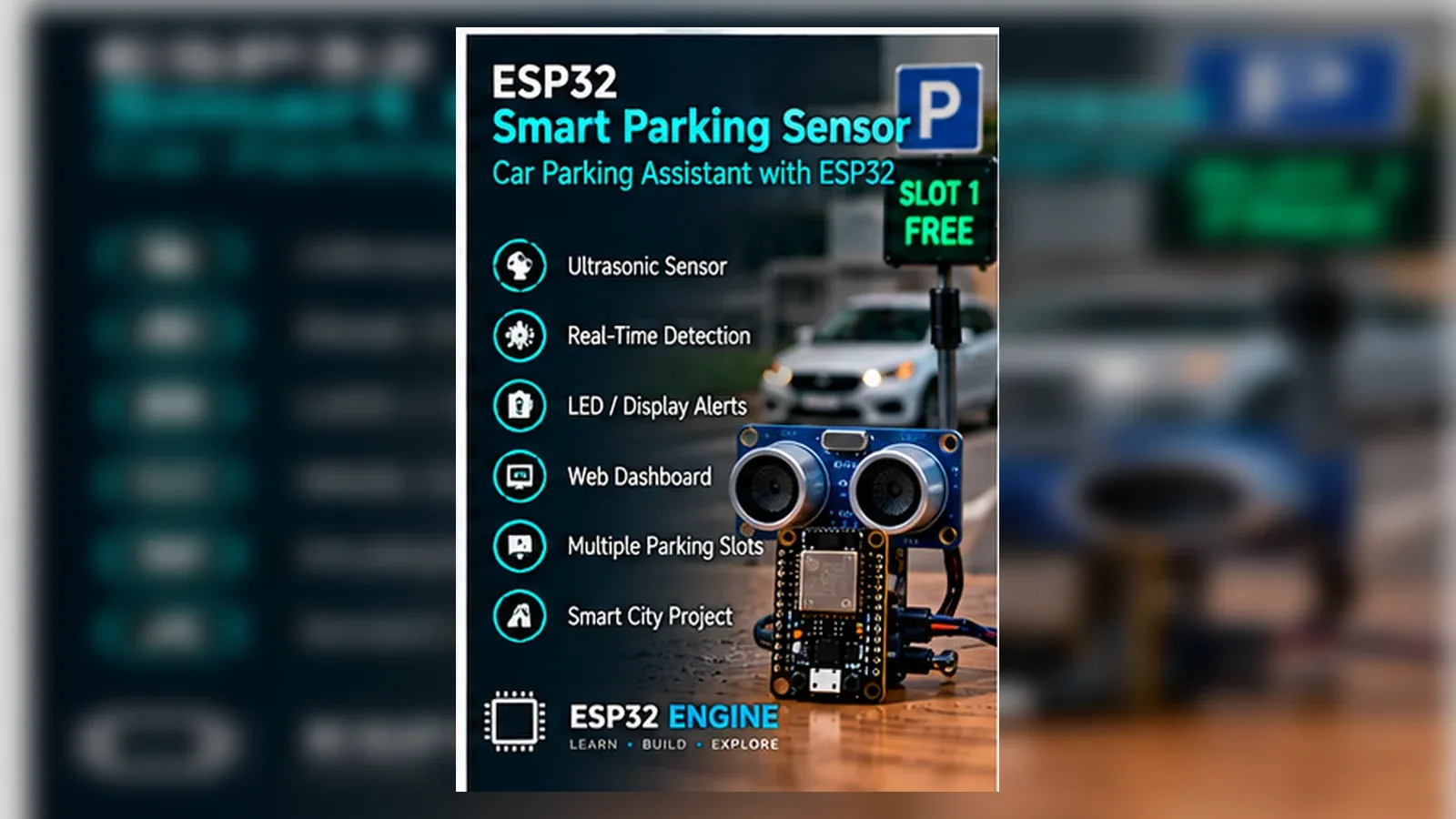
Build a Smart Parking Sensor
The Story
ESP32 Smart Parking Sensor solves a real beginner problem: turning an ESP32 reading into a useful physical or networked result. Build this if you want a practical distance-sensing project that teaches timing, voltage protection, and threshold decisions.
The tutorial focuses on the engineering path: prove the input, understand the circuit, write readable code, then test the output under real conditions. Treat this as a bench prototype for learning, not a weatherproof or road-approved automotive device.
Explain Like I'm 12
The ultrasonic sensor works like a bat calling into a space and listening for the echo. The ESP32 measures how long the echo takes to return and decides whether a car is close enough to count as parked.
Safety Standards
- Unplug USB before changing jumper wires. Recheck 3.3 V, 5 V, and GND before reconnecting power.
- Do not power motors, pumps, LED strips, or servos from the ESP32 3.3 V pin. Use a suitable external supply and common ground.
- Breadboards are for low-current prototypes. Move high-current or unattended builds to proper terminals, enclosure, strain relief, and fusing.
What You Will Build
An educational parking-bay prototype that measures distance with an HC-SR04 ultrasonic sensor, protects ECHO with a 10 kOhm / 20 kOhm divider before GPIO18, and uses green/red LEDs or a dashboard output to show whether the bay is free or occupied.
Learning Objectives
- Trigger an HC-SR04 sensor from an ESP32.
- Protect the ESP32 input from a 5 V echo signal.
- Convert echo time into distance in centimeters.
- Choose a parking threshold from measured data.
- Use LEDs or displays to communicate occupied/free status.
Components List
- 1× ESP32 DevKit V1Required for this build
- 1× HC-SR04 ultrasonic sensor5 V; use voltage divider on ECHO pin
- 1× Green LED 5 mmBay free indicator
- 1× Red LED 5 mmBay occupied indicator
- 2× 220 ohm resistorLED current limiting
- 1× 10 kohm and 20 kohm resistorVoltage divider for ECHO pin
- 1× Breadboard and jumper wiresRequired for this build
- USB data cableProgramming and bench power
Bill of Materials
| Part | Qty | Estimated Cost | Notes |
|---|---|---|---|
| 1× ESP32 DevKit V1 | 1 | Varies | Required for this build |
| 1× HC-SR04 ultrasonic sensor | 1 | Varies | 5 V; use voltage divider on ECHO pin |
| 1× Green LED 5 mm | 1 | Varies | Bay free indicator |
| 1× Red LED 5 mm | 1 | Varies | Bay occupied indicator |
| 2× 220 ohm resistor | 1 | Varies | LED current limiting |
| 1× 10 kohm and 20 kohm resistor | 1 | Varies | Voltage divider for ECHO pin |
Wiring
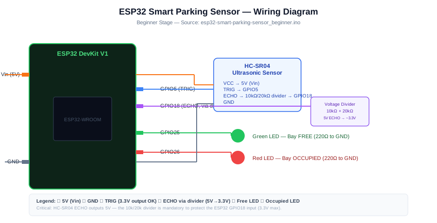
Wire the HC-SR04 first, confirm readings in Serial Monitor, then connect the LED output hardware. GPIO5 sends the trigger pulse, GPIO18 reads ECHO only after the 10 kOhm / 20 kOhm divider, and the threshold decides free or occupied.
-
1
Unplug USB before changing wires.
-
2
Connect HC-SR04 TRIG to GPIO 5 (3.3 V output is sufficient for trigger).
-
3
Connect HC-SR04 ECHO to GPIO 18 via divider (ECHO is 5 V; divide with 10k+20k to 3.3 V).
-
4
Connect HC-SR04 VCC to 5 V (Vin).
-
5
Connect HC-SR04 GND to GND.
-
6
Connect Green LED anode to GPIO 25 (220 ohm resistor).
-
7
Connect Red LED anode to GPIO 26 (220 ohm resistor).
-
8
Reconnect USB, upload the sketch, and open Serial Monitor at 115200 baud unless the code says otherwise.
GPIO Mapping
| Signal | ESP32 Pin | Direction | Notes |
|---|---|---|---|
| HC-SR04 TRIG | GPIO 5 | Output | 3.3 V output is sufficient for trigger |
| HC-SR04 ECHO | GPIO 18 via divider | Input | ECHO is 5 V; divide with 10k+20k to 3.3 V |
| HC-SR04 VCC | 5 V (Vin) | Power | Match this wire to the code constant. |
| HC-SR04 GND | GND | Ground | Match this wire to the code constant. |
| Green LED anode | GPIO 25 | Output | 220 ohm resistor |
| Red LED anode | GPIO 26 | Output | 220 ohm resistor |
Circuit Explanation
GPIO5 sends a short trigger pulse. The HC-SR04 sends back an echo pulse whose width represents distance. Because many HC-SR04 modules output 5 V on ECHO, the signal must be reduced to 3.3 V before it enters the ESP32. LEDs on separate GPIO pins show the bay state.
Engineering Explanation
Ultrasonic parking sensors are time-of-flight systems. They work best when the target surface reflects sound back toward the sensor. Angle, height, wind, nearby sensors, and soft surfaces can all affect readings, so a reliable parking project uses averaging, timeout handling, and a threshold measured from the real bay. In this beginner build BAY_THRESHOLD_CM is 50 cm, but the correct value should come from your own empty-bay and occupied-bay Serial Monitor readings.
Libraries
- Arduino ESP32 coreInstall ESP32 board support in Arduino IDE.
Code
Copy into Arduino IDE. Install any libraries noted in the component guides first.
// ESP32 Smart Parking Sensor - Beginner
// Single bay HC-SR04 distance + LED status

const int TRIG = 5;
const int ECHO = 18;
const int LED_FREE = 25;
const int LED_OCC  = 26;
const float BAY_THRESHOLD_CM = 50.0; // Vehicle present if closer than this

long measureCm() {
  digitalWrite(TRIG, LOW);
  delayMicroseconds(2);
  digitalWrite(TRIG, HIGH);
  delayMicroseconds(10);
  digitalWrite(TRIG, LOW);
  long duration = pulseIn(ECHO, HIGH, 30000); // 30 ms timeout
  if (duration == 0) return -1; // No echo received
  return duration * 0.034 / 2; // Convert to cm
}

void setup() {
  Serial.begin(115200);
  pinMode(TRIG, OUTPUT);
  pinMode(ECHO, INPUT);
  pinMode(LED_FREE, OUTPUT);
  pinMode(LED_OCC,  OUTPUT);
}

void loop() {
  long dist = measureCm();
  bool occupied = (dist > 0 && dist < BAY_THRESHOLD_CM);

  Serial.printf("Distance: %ld cm  Bay: %sn",
    dist, occupied ? "OCCUPIED" : "FREE");

  digitalWrite(LED_FREE, occupied ? LOW  : HIGH);
  digitalWrite(LED_OCC,  occupied ? HIGH : LOW);
  delay(500);
}
Code Explanation
The sketch starts Serial Monitor, defines readable pin constants, configures input and output pins in setup(), then repeats the measurement and decision logic in loop(). The loop prints the live reading first, compares it with a threshold, then changes the output. Printing before controlling the output makes debugging much easier because you can see what the ESP32 believes is happening.
Expected Output
Serial Monitor prints Distance values and FREE or OCCUPIED status. With the bay clear, the green LED should be on. When a target is closer than BAY_THRESHOLD_CM, the red LED turns on. If readings are -1, debug the HC-SR04 wiring and ECHO divider before trusting the LEDs.
Troubleshooting
- Distance reads 0 or -1 Check TRIG/ECHO wiring, confirm the voltage divider, and make sure the sensor has 5 V power.
- Occupied/free state flickers Average five readings and require the same result twice before changing state.
- Low vehicles are missed Mount the sensor lower or angle it toward the bonnet or bumper area.
- Adjacent sensors interfere Trigger sensors one at a time with a delay between measurements.
Common Mistakes
- Connecting HC-SR04 ECHO directly to an ESP32 pin without level shifting.
- Mounting the sensor too high for low vehicles.
- Using one reading instead of averaging several readings.
- Forgetting that angled surfaces can reflect sound away from the receiver.
- Using a threshold copied from another parking bay.
Testing Checklist
- Upload a simple Blink sketch first to confirm the board and USB cable work.
- Wire only power and ground, then confirm the board still boots.
- Connect the input signal and print raw readings before using thresholds.
- Trigger the real-world condition slowly and watch Serial Monitor.
- Connect the output only after the input reading is believable.
- Power-cycle the project and confirm it starts in a safe state.
Engineering Tips
- Use a voltage divider or level shifter on ECHO.
- Measure empty-bay distance first, then set the threshold below that value.
- Use timeout handling so missing echoes do not create false readings.
- Avoid firing multiple ultrasonic sensors at the same time.
- Add weather protection for outdoor installations.
Performance Tips
- Use median or average filtering for stable distance.
- Scan multiple bays sequentially.
- Reduce update rate for dashboards to avoid unnecessary Wi-Fi traffic.
- Store last known state if a single reading times out.
Upgrade Ideas
- Add a 4-digit 7-segment display to show remaining free spaces in a multi-bay system
- Add Wi-Fi and publish bay status to a web dashboard
- Add a buzzer that sounds when a vehicle parks in a reserved bay
- Add a second sensor to detect if a vehicle is entering or leaving the bay
Real-World Applications
- Driveway parking assist
- Garage wall distance indicator
- Small car park occupancy counter
- Loading bay availability system
Downloads
- ESP32 Smart Parking Sensor Arduino sketchUse the code section as the source sketch.
- Bench test checklistFollow the testing checklist before permanent installation.
FAQs
Why does HC-SR04 ECHO need a voltage divider?
The project wires ECHO through a 10 kOhm and 20 kOhm divider because HC-SR04 ECHO is a 5 V signal and ESP32 GPIO inputs are 3.3 V logic.
Why does the occupied/free state flicker?
Ultrasonic readings change with angle, distance, and reflections. Average several readings and add a small gap between occupied and free thresholds.
Can one sensor detect every vehicle position?
No. Low vehicles, angled surfaces, and off-center parking can reflect sound away from the receiver, so sensor placement matters.
Review, Testing, and References
Author: Abdul Mubeen and the ESP32 Engine editorial team. Last updated: 2026-08-22. Reviewed: wiring logic, Arduino code structure, beginner safety, and learning sequence.
Educational level: Beginner. Estimated completion time: 60-90 min. This project is for learning and prototyping; production or unattended hardware needs additional engineering review.
Project Complete!
You completed ESP32 Smart Parking Sensor as a real ESP32 engineering build, not just a wiring demo. You now know how to test the input, protect the circuit, explain the code, and improve the project safely.
- Read and verify project input hardware
- Map signals to safe ESP32 GPIO pins
- Debug with Serial Monitor
- Apply safety and performance checks
- Plan the next learning step