
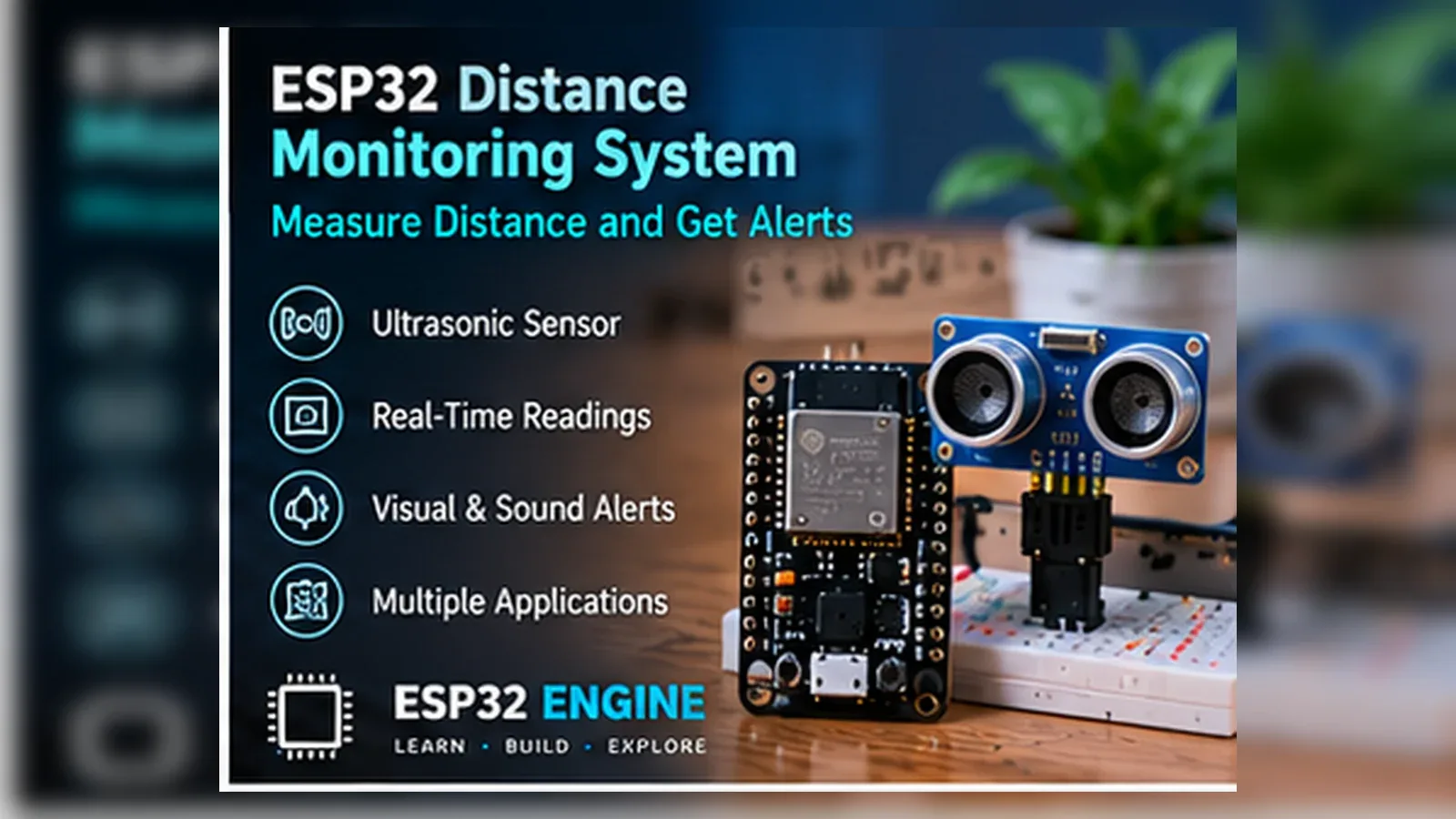
Build a Distance Alert Meter
The Story
Distance projects are useful because the result is immediate: move an object and the ESP32 reacts. This build documents the important voltage detail, because the HC-SR04 ECHO line must be divided before it reaches GPIO18. The component list, wiring table, GPIO map, code constants, expected output, troubleshooting, and FAQ now describe the same bench build so a learner can verify each step instead of guessing.
Explain Like I'm 12
The HC-SR04 sends a tiny sound pulse and waits for the echo. A short wait means the object is close, so the ESP32 turns on the buzzer. Prove the local wiring and code first, then add displays, logging, or Wi-Fi after the simple version behaves exactly as expected.
Safety Standards
- Unplug USB before changing jumper wires. Recheck 3.3 V, 5 V, and GND before reconnecting power.
- Do not power motors, pumps, LED strips, or servos from the ESP32 3.3 V pin. Use a suitable external supply and common ground.
- Breadboards are for low-current prototypes. Move high-current or unattended builds to proper terminals, enclosure, strain relief, and fusing.
What You Will Build
An ESP32 HC-SR04 distance monitor that prints live centimeter readings in Serial Monitor, protects the 5 V ECHO signal with a 10 kOhm / 20 kOhm divider before GPIO18, and sounds a buzzer on GPIO25 when an object is closer than the limit.
Learning Objectives
- Wire the exact GPIO pins used by the sketch.
- Run the starter code and compare output with the wiring table.
- Explain the main sensor or input signal in plain language.
- Troubleshoot one wiring mistake using Serial Monitor evidence.
Components List
- ESP32 DevKit boardRuns the timing code and buzzer output.
- HC-SR04 ultrasonic sensor5 V distance sensor; ECHO must go through a divider before GPIO18.
- 10 kOhm resistorUpper resistor in the ECHO voltage divider.
- 20 kOhm resistorLower resistor in the ECHO voltage divider.
- Small buzzer moduleAlert output on GPIO25.
Bill of Materials
| Part | Qty | Estimated Cost | Notes |
|---|---|---|---|
| ESP32 DevKit board | 1 | Varies | Runs the timing code and buzzer output. |
| HC-SR04 ultrasonic sensor | 1 | Varies | 5 V distance sensor; ECHO must go through a divider before GPIO18. |
| 10 kOhm resistor | 1 | Varies | Upper resistor in the ECHO voltage divider. |
| 20 kOhm resistor | 1 | Varies | Lower resistor in the ECHO voltage divider. |
| Small buzzer module | 1 | Varies | Alert output on GPIO25. |
Wiring
An ESP32 distance monitor that triggers an HC-SR04 from GPIO5, reads ECHO on GPIO18 through a 10 kOhm / 20 kOhm divider, and sounds a buzzer on GPIO25.
-
1
Unplug USB before changing the HC-SR04 or divider wiring.
-
2
Connect HC-SR04 VCC to 5V and GND to GND.
-
3
Connect HC-SR04 TRIG to GPIO5.
-
4
Connect HC-SR04 ECHO through the 10 kOhm / 20 kOhm divider, with the divided node going to GPIO18.
-
5
Connect buzzer signal or positive input to GPIO25 and buzzer ground to GND.
-
6
Reconnect USB and open Serial Monitor at 115200 baud.
GPIO Mapping
| Signal | ESP32 Pin | Direction | Notes |
|---|---|---|---|
| HC-SR04 TRIG | GPIO5 | Output | Short trigger pulse. |
| HC-SR04 ECHO | GPIO18 | Input | Read through a 10 kOhm / 20 kOhm divider. |
| HC-SR04 VCC | 5 V / VIN | Power | Powers the common 5 V HC-SR04 module. |
| HC-SR04 GND | GND | Ground | Common ground is required for timing and buzzer output. |
| Buzzer alert | GPIO25 | Output | Turns on below DISTANCE_LIMIT_CM. |
Circuit Explanation
GPIO5 creates the trigger pulse. The divided ECHO pulse reaches GPIO18, and GPIO25 drives the alert output.
Engineering Explanation
GPIO5 sends a 10 microsecond trigger pulse. The HC-SR04 raises ECHO while it waits for the sound reflection, and GPIO18 measures that pulse after the divider has reduced it to ESP32-safe logic. The code returns duration / 58, a common centimeter shortcut for the round trip of sound. DISTANCE_LIMIT_CM is 20 cm in the sketch. pulseIn() uses a timeout so a missing echo returns -1 instead of blocking forever.
Libraries
- Arduino ESP32 coreInstall ESP32 board support in Arduino IDE.
Code
Copy into Arduino IDE. Install any libraries noted in the component guides first.
// ESP32 Distance Monitoring System - HC-SR04
const int TRIG_PIN = 5;
const int ECHO_PIN = 18;
const int BUZZER_PIN = 25;
const int DISTANCE_LIMIT_CM = 20;

long readDistanceCm() {
  digitalWrite(TRIG_PIN, LOW);
  delayMicroseconds(2);
  digitalWrite(TRIG_PIN, HIGH);
  delayMicroseconds(10);
  digitalWrite(TRIG_PIN, LOW);
  long duration = pulseIn(ECHO_PIN, HIGH, 30000);
  if (duration == 0) return -1;
  return duration / 58;
}

void setup() {
  Serial.begin(115200);
  pinMode(TRIG_PIN, OUTPUT);
  pinMode(ECHO_PIN, INPUT);
  pinMode(BUZZER_PIN, OUTPUT);
}

void loop() {
  long distanceCm = readDistanceCm();
  Serial.print("Distance cm: ");
  Serial.println(distanceCm);
  digitalWrite(BUZZER_PIN, distanceCm > 0 && distanceCm < DISTANCE_LIMIT_CM ? HIGH : LOW);
  delay(250);
}
Code Explanation
readDistanceCm() sends the trigger pulse, measures ECHO, and converts the timing to centimeters. loop() turns the buzzer on only for valid readings below 20 cm.
Expected Output
Serial Monitor prints distance values in centimeters. With no echo it prints -1 and the buzzer stays off. When an object moves closer than 20 cm, GPIO25 turns the buzzer on.
Troubleshooting
- Distance always reads -1 Check TRIG on GPIO5, divided ECHO on GPIO18, 5 V sensor power, and common ground.
- Values jump around Aim at a flat surface and shorten jumper wires.
- Buzzer never turns on Move an object under 20 cm and verify buzzer signal is on GPIO25.
Common Mistakes
- Connecting HC-SR04 ECHO directly to the ESP32 without the divider.
- Swapping TRIG and ECHO pins.
- Forgetting common ground.
Testing Checklist
- Upload the sketch with only the documented circuit attached.
- Open Serial Monitor and confirm the expected messages.
- Move or trigger the input and watch the output change.
- Power-cycle the project and confirm it starts safely.
Engineering Tips
- Change one variable at a time.
- Keep wires short and labeled while testing.
- Record any calibrated threshold before installing the project.
Upgrade Ideas
- Show distance on an OLED display.
- Add separate near, caution, and clear thresholds.
- Log distance over Wi-Fi after local readings are stable.
Real-World Applications
- Classroom lab build
- Bench prototype
- Local ESP32 learning project
FAQs
Why is the divider required?
ESP32 GPIO is 3.3 V logic, while HC-SR04 ECHO can be 5 V.
Can I change the alert distance?
Yes. Change DISTANCE_LIMIT_CM and keep the documentation in sync.
Why does the reading show -1?
The sketch returns -1 when no echo arrives before the timeout.
Review, Testing, and References
Author: Abdul Mubeen and the ESP32 Engine editorial team. Last updated: 2026-08-26. Reviewed: wiring logic, Arduino code structure, beginner safety, and learning sequence.
Educational level: Beginner. Estimated completion time: 60-75 min. This project is for learning and prototyping; production or unattended hardware needs additional engineering review.
Project Complete!
You completed ESP32 Distance Monitoring System as a real ESP32 engineering build with matching wiring, code, testing, and troubleshooting.
- Read the GPIO map
- Verify code against hardware
- Troubleshoot with Serial Monitor