
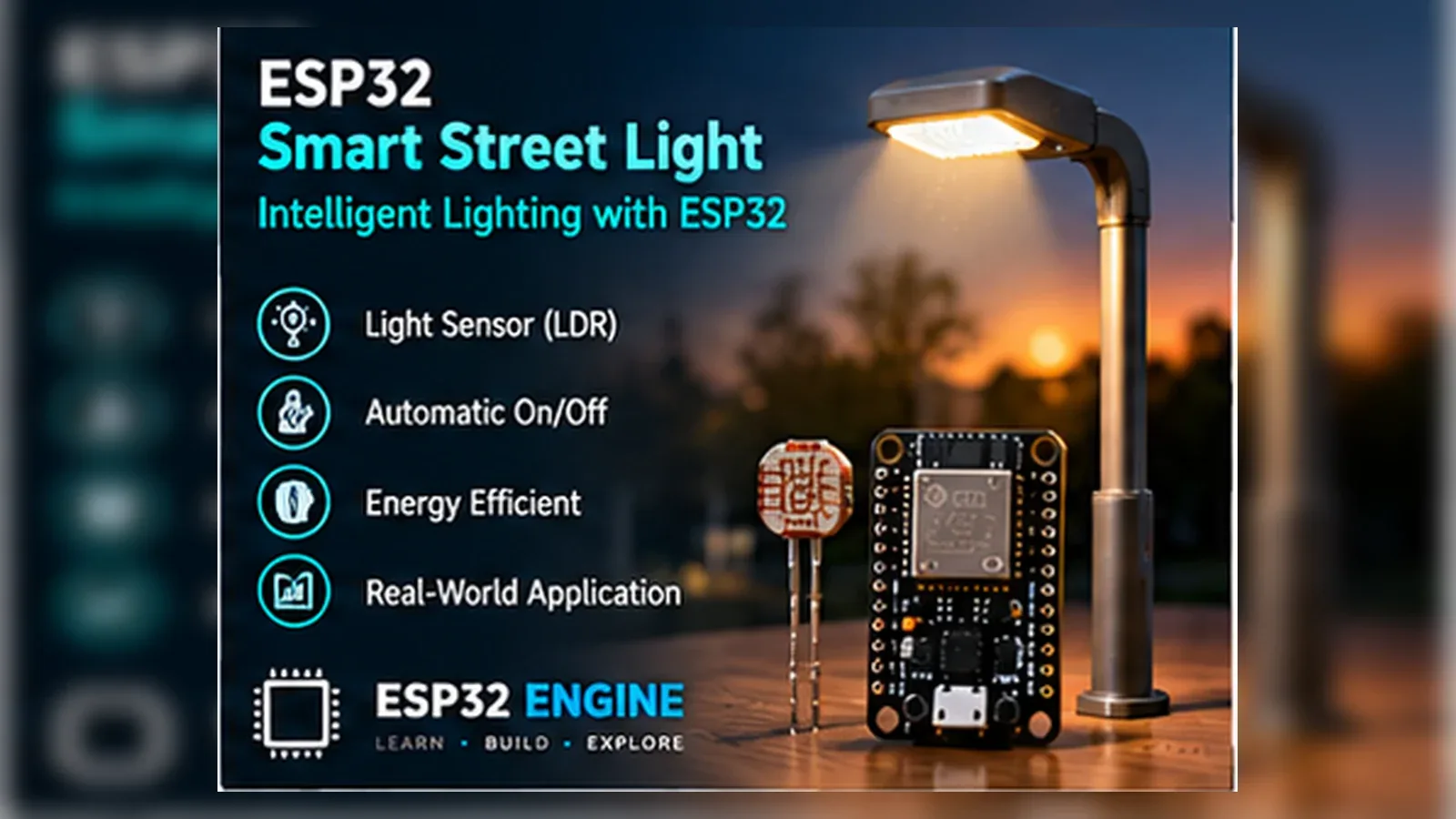
Build a Smart Street Light
The Story
ESP32 Smart Street Light solves a real beginner problem: turning an ESP32 reading into a useful physical or networked result. Build this to learn LDR analog sensing, relay/driver control, hysteresis, and smart-city style automation.
The tutorial focuses on the engineering path: prove the input, understand the circuit, write readable code, then test the output under real conditions.
Explain Like I'm 12
The LDR is the project eye. In daylight it tells the ESP32 the area is bright; after sunset the number changes and the code decides the street light should turn on.
Safety Standards
- Unplug USB before changing jumper wires. Recheck 3.3 V, 5 V, and GND before reconnecting power.
- Do not power motors, pumps, LED strips, or servos from the ESP32 3.3 V pin. Use a suitable external supply and common ground.
- Breadboards are for low-current prototypes. Move high-current or unattended builds to proper terminals, enclosure, strain relief, and fusing.
- Relay and mains-voltage projects require isolation, correct relay ratings, enclosed wiring, and qualified adult supervision.
What You Will Build
A light-sensing ESP32 street light prototype that reads an LDR voltage divider on GPIO33, prints live light readings, compares them with a night threshold, and drives a relay module or low-voltage lamp control signal on GPIO25.
Learning Objectives
- Read an LDR voltage divider with ESP32 analog input.
- Use a threshold and hysteresis for stable day/night control.
- Drive a relay or transistor-controlled lamp output safely.
- Understand why sensor placement matters outdoors.
- Add motion-based brightness logic as an upgrade.
Components List
- ESP32 Dev BoardRequired for this build
- Ldr SensorLight-level input for day/night decisions
- Relay module or low-voltage lamp driverOutput controlled from GPIO25
- Low-voltage lamp supplyUse a safe bench load for learning
- Breadboard and jumper wiresFor safe low-voltage prototyping
- USB data cableProgramming and bench power
Bill of Materials
| Part | Qty | Estimated Cost | Notes |
|---|---|---|---|
| ESP32 Dev Board | 1 | Varies | Required for this build |
| Ldr Sensor | 1 | Varies | Required for this build |
| Street Light Relay | 1 | Varies | Required for this build |
| 5V Power Supply | 1 | Varies | Required for this build |
| Breadboard and jumper wires | 1 set | Varies | For safe low-voltage prototyping |
Wiring
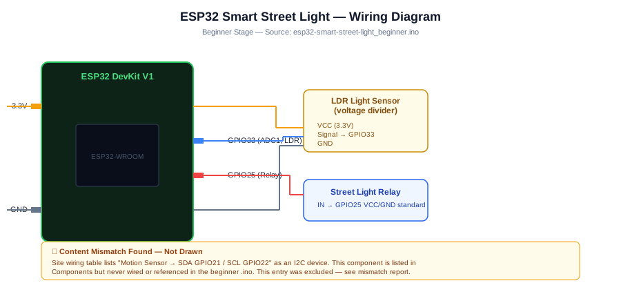
Wire the LDR input first, confirm day and night readings in Serial Monitor, then connect the GPIO25 output to a relay module or low-voltage lamp driver. Do not put mains lighting on a breadboard.
-
1
Unplug USB before changing wires.
-
2
Connect Ldr Sensor signal to GPIO33.
-
3
Connect the relay module input or low-voltage lamp driver control to GPIO25.
-
4
Connect VCC to 3.3V/5V.
-
5
Connect GND to GND.
-
6
Reconnect USB, upload the sketch, and open Serial Monitor at 115200 baud unless the code says otherwise.
GPIO Mapping
| Signal | ESP32 Pin | Direction | Notes |
|---|---|---|---|
| Ldr Sensor signal | GPIO33 | Input | Match this wire to the code constant. |
| Relay or lamp driver control | GPIO25 | Output | Control signal only; use a proper module or driver for the lamp side. |
| VCC | 3.3V/5V | Power | Match this wire to the code constant. |
| GND | GND | Ground | Match this wire to the code constant. |
Circuit Explanation
An LDR forms a voltage divider so changing light becomes changing voltage. The ESP32 reads that voltage on an ADC pin. A relay or driver pin controls the lamp side, but actual lamps need a properly rated isolated module and safe enclosure.
Engineering Explanation
Outdoor lighting controllers need hysteresis because light changes gradually at sunrise and sunset. Without hysteresis the output may chatter around the threshold. Professional systems also separate sensor placement from lamp glare so the light does not fool its own sensor.
Libraries
- Arduino ESP32 coreInstall ESP32 board support in Arduino IDE.
Code
Copy into Arduino IDE. Install any libraries noted in the component guides first.
// ESP32 Street Light for Urban Node
const int SENSOR_PIN = 33;
const int OUTPUT_PIN = 25;
const int THRESHOLD = 1812;
const int SAMPLE_DELAY_MS = 300;

void setup() {
  Serial.begin(115200);
  pinMode(OUTPUT_PIN, OUTPUT);
  pinMode(SENSOR_PIN, INPUT);
  Serial.println("Starting: street light for urban node");
  Serial.print("Threshold: ");
  Serial.println(THRESHOLD);
}

void loop() {
  int reading = analogRead(SENSOR_PIN);
  Serial.print("Ldr Sensor signal: ");
  Serial.println(reading);
  bool active = reading < THRESHOLD;
  digitalWrite(OUTPUT_PIN, active ? HIGH : LOW);
  delay(SAMPLE_DELAY_MS);
}
Code Explanation
The sketch starts Serial Monitor, defines readable pin constants, configures input and output pins in setup(), then repeats the measurement and decision logic in loop(). The loop prints the live reading first, compares it with a threshold, then changes the output. Printing before controlling the output makes debugging much easier because you can see what the ESP32 believes is happening.
Expected Output
Serial Monitor should print "Starting: street light for urban node", show the threshold, then print live LDR readings. Covering the LDR should move the reading below the threshold and turn the GPIO25 output on; bright light should turn it off.
Build Photos
- Breadboard overviewShow ESP32, module, output device, and power rails.
- Close-up wiringShow signal pins clearly enough for learners to compare.
- Working outputShow Serial Monitor, LEDs, display, or dashboard after the condition changes.
Troubleshooting
- Light turns on and off repeatedly Add hysteresis and move the LDR away from the lamp beam.
- Relay does not click Use a relay module with proper VCC, GND, IN wiring and common ground. Some relay modules are active LOW, so test the module before connecting any load.
- Analog reading is stuck Check the voltage divider: the LDR and fixed resistor must not both go to the same rail.
- Output switches at the wrong light level Record Serial Monitor readings in bright light and covered or dark conditions, then adjust THRESHOLD between those two real values.
- Motion sensor retriggers oddly Give PIR modules warm-up time and avoid pointing them at heat sources.
Common Mistakes
- Pointing the LDR at the lamp it controls.
- Switching a mains light on a breadboard.
- Skipping hysteresis and creating relay chatter.
- Powering a relay coil from a GPIO pin.
- Using ADC2 pins while Wi-Fi is active.
Testing Checklist
- Upload a simple Blink sketch first to confirm the board and USB cable work.
- Wire only power and ground, then confirm the board still boots.
- Connect the input signal and print raw readings before using thresholds.
- Trigger the real-world condition slowly and watch Serial Monitor.
- Connect the output only after the input reading is believable.
- Power-cycle the project and confirm it starts in a safe state.
Engineering Tips
- Use an LDR divider with a known resistor such as 10 kOhm.
- Keep high-voltage lamp wiring out of breadboards.
- Add hysteresis before adding Wi-Fi.
- Test the LDR reading with a flashlight and by covering it with your hand.
- Use a MOSFET for low-voltage LED strips and a relay only when isolation is needed.
Performance Tips
- Sample light every few seconds; daylight does not change millisecond by millisecond.
- Use deep sleep for solar prototypes.
- Dim LEDs with PWM instead of hard switching when using low-voltage lighting.
- Publish only state changes to save network traffic.
Upgrade Ideas
- Publish readings to an MQTT broker or Home Assistant
- Add motion-based dimming with a PIR sensor.
Real-World Applications
- Solar street light controller prototype
- Porch or garden lighting automation
- Smart city classroom model
- Warehouse aisle lighting demonstration
Downloads
- ESP32 Smart Street Light Arduino sketchUse the code section as the source sketch.
- Bench test checklistFollow the testing checklist before permanent installation.
FAQs
Why does the light turn on and off repeatedly?
Relay chatter usually means the LDR reading is near the threshold or the lamp is shining back onto the sensor. Add hysteresis and point the LDR away from the controlled light.
Can I switch a household street light with this breadboard build?
No. This tutorial is a low-voltage learning build only. Do not connect mains-powered lamps or outdoor wiring to a breadboard relay circuit.
Why is the analog reading stuck?
Check the LDR module power, ground, signal wire, and GPIO33 connection before changing thresholds in the sketch.
Review, Testing, and References
Author: Abdul Mubeen and the ESP32 Engine editorial team. Last updated: 2026-08-26. Reviewed: wiring logic, Arduino code structure, beginner safety, and learning sequence.
Educational level: Beginner. Estimated completion time: 70-100 min. This project is for learning and prototyping; production or unattended hardware needs additional engineering review.
Project Complete!
You completed ESP32 Smart Street Light as a real ESP32 engineering build, not just a wiring demo. You now know how to test the input, protect the circuit, explain the code, and improve the project safely.
- Read and verify project input hardware
- Map signals to safe ESP32 GPIO pins
- Debug with Serial Monitor
- Apply safety and performance checks
- Plan the next learning step