
Build an Educational Lightning Sensor Demo
The Story
This is a technically honest lightning-sensor lesson. It is not weather forecasting, protection equipment, or a certified alert device.
Explain Like I'm 12
Lightning makes radio noise. The AS3935 listens for patterns like that, but other electronics can also make noise, so the ESP32 labels what the chip reports.
Learning Support
- Recommended ageAges 14+
- Adult supervisionAdult supervision required; do not test outdoors during storms.
- Classroom useUse the project indoors as a sensor-classification, tuning, and false-positive discussion, not as a storm alert.
- Parent promptAsk why official weather alerts matter more than a hobby sensor.
- Screen-free activityDraw noise, disturber, and lightning-like event categories.
- Next challengeAdd timestamped local logging after the sensor is stable indoors.
- Skills practiced
- SPI wiring
- Interrupt handling
- Noise classification
- Safety limitations
- Learning outcomes
- Wire AS3935 SPI on GPIO5/GPIO18/GPIO23/GPIO19.
- Use GPIO4 as the interrupt input.
- Distinguish noise, disturber, and lightning-like events.
- Explain false positives and life-safety limits.
- Mini experiments
- Change noise level setting indoors.
- Move the module away from power supplies.
- Log event types without storm claims.
Safety Standards
- Follow official weather alerts and local guidance for storm decisions; this hobby circuit is educational only.
- Do not go outdoors, handle antennas, or move wiring during thunder or lightning.
- Keep the AS3935, ESP32, OLED, and LED on low-voltage bench power. Unplug USB before changing SPI, IRQ, OLED, or LED wiring.
What You Will Build
An ESP32 AS3935 educational lightning sensor demo that classifies noise, disturber, and lightning-like events, flashes an LED for lightning-like events, and displays distance codes on an OLED.
Learning Objectives
- Wire AS3935 SPI on GPIO5/GPIO18/GPIO23/GPIO19.
- Use GPIO4 as the interrupt input.
- Distinguish noise, disturber, and lightning-like events.
- Explain false positives and life-safety limits.
Components List
- ESP32 DevKit boardUSB-programmable ESP32 board for the low-voltage logic side.
- AS3935 lightning sensor moduleSPI-capable module powered at 3.3 V unless the breakout states otherwise.
- SSD1306 OLED displayOptional I2C status display on GPIO21/GPIO22.
- Red LED and 220 ohm resistorEvent indicator on GPIO26.
- Breadboard and jumper wiresKeep sensor away from noisy power wiring.
Bill of Materials
| Part | Qty | Estimated Cost | Notes |
|---|---|---|---|
| ESP32 DevKit board | 1 | Varies | USB-programmable ESP32 board for the low-voltage logic side. |
| AS3935 lightning sensor module | 1 | Varies | SPI-capable module powered at 3.3 V unless the breakout states otherwise. |
| SSD1306 OLED display | 1 | Varies | Optional I2C status display on GPIO21/GPIO22. |
| Red LED and 220 ohm resistor | 1 | Varies | Event indicator on GPIO26. |
| Breadboard and jumper wires | 1 | Varies | Keep sensor away from noisy power wiring. |
Wiring
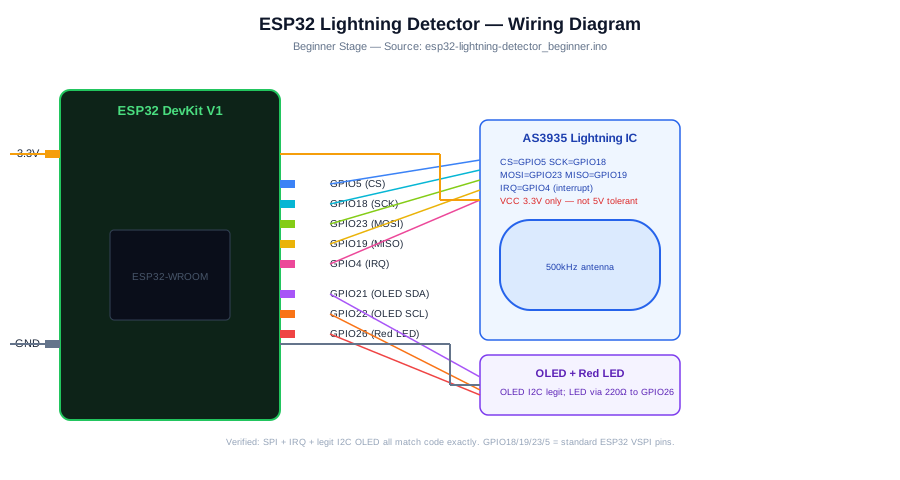
AS3935 uses SPI CS GPIO5, SCK GPIO18, MOSI GPIO23, MISO GPIO19, and IRQ GPIO4. OLED uses I2C GPIO21/GPIO22.
-
1
Unplug USB before wiring.
-
2
Connect AS3935 VCC to 3.3 V and GND to GND.
-
3
Connect AS3935 CS to GPIO5, SCK to GPIO18, MOSI to GPIO23, and MISO to GPIO19.
-
4
Connect AS3935 IRQ to GPIO4.
-
5
Connect OLED SDA to GPIO21 and SCL to GPIO22.
-
6
Connect the red LED through 220 ohm resistor to GPIO26.
GPIO Mapping
| Signal | ESP32 Pin | Direction | Notes |
|---|---|---|---|
| AS3935 CS | GPIO5 | SPI chip select | Keep stable during boot. |
| AS3935 SCK | GPIO18 | SPI clock | VSPI clock. |
| AS3935 MOSI | GPIO23 | SPI MOSI | ESP32 to sensor. |
| AS3935 MISO | GPIO19 | SPI MISO | Sensor to ESP32. |
| AS3935 IRQ | GPIO4 | Input | Interrupt event line. |
| Event LED | GPIO26 | Output | Series resistor required. |
| OLED SDA/SCL | GPIO21/GPIO22 | I2C | Optional display. |
Circuit Explanation
The AS3935 raises its IRQ pin when it has an event to report. The ESP32 then reads the interrupt register over SPI and classifies the event as noise, disturber, or lightning-like. Noise means the sensor floor is too noisy for a clean decision. Disturber means an electrical pulse looked storm-like but did not pass the chip's lightning checks. Lightning-like means the AS3935 algorithm accepted the pattern and can return a distance code.
Engineering Explanation
Indoor and outdoor modes change the AS3935 analog front-end gain, so the same wiring can behave differently on a desk, near electronics, or outside under cover. Start indoors with disturbers unmasked so you can see interference instead of hiding it. Tune noise level and spike rejection one step at a time, record the false-positive rate, then decide whether the setting is too sensitive or too quiet. The distance value is a sensor code in kilometers from the AS3935 algorithm, not a verified strike location or a safety radius.
Libraries
- SparkFun AS3935Install SparkFun AS3935 Lightning Detector library.
- Adafruit SSD1306For OLED output.
Code
Copy into Arduino IDE. Install any libraries noted in the component guides first.
// ESP32 AS3935 educational lightning sensor demo
// Not a life-safety warning system. Follow official weather alerts.
#include <SPI.h>
#include <Wire.h>
#include <Adafruit_SSD1306.h>
#include <SparkFun_AS3935.h>

const int AS3935_CS = 5;
const int AS3935_IRQ = 4;
const int LED_PIN = 26;

SparkFun_AS3935 lightning(AS3935_CS);
Adafruit_SSD1306 oled(128, 64, &Wire, -1);

volatile bool eventFlag = false;

void IRAM_ATTR onAs3935Event() {
  eventFlag = true;
}

void setup() {
  Serial.begin(115200);
  Wire.begin(21, 22);
  SPI.begin(18, 19, 23, AS3935_CS);
  oled.begin(SSD1306_SWITCHCAPVCC, 0x3C);
  oled.setTextColor(WHITE);
  pinMode(LED_PIN, OUTPUT);
  pinMode(AS3935_IRQ, INPUT);

  if (!lightning.beginSPI(AS3935_CS, 2000000)) {
    Serial.println("AS3935 not found. Check SPI wiring and 3.3 V power.");
    while (true) delay(10);
  }

  lightning.setIndoorOutdoor(INDOOR);
  lightning.maskDisturber(false);
  lightning.setNoiseLevel(2);
  lightning.spikeRejection(2);
  attachInterrupt(digitalPinToInterrupt(AS3935_IRQ), onAs3935Event, RISING);

  Serial.println("AS3935 demo ready. Do not test outdoors during storms.");
}

void loop() {
  if (!eventFlag) return;
  eventFlag = false;
  delay(5);

  int type = lightning.readInterruptReg();
  if (type == NOISE_INT) {
    Serial.println("Noise event. Move the sensor away from electronics or raise noise level.");
  } else if (type == DISTURBER_INT) {
    Serial.println("Disturber event. Electrical interference, not confirmed lightning.");
  } else if (type == LIGHTNING_INT) {
    int distanceKm = lightning.distanceToStorm();
    Serial.print("Lightning-like event. AS3935 distance code: ");
    Serial.print(distanceKm);
    Serial.println(" km. Not a verified strike distance.");

    digitalWrite(LED_PIN, HIGH);
    delay(100);
    digitalWrite(LED_PIN, LOW);

    oled.clearDisplay();
    oled.setTextSize(1);
    oled.setCursor(0, 0);
    oled.println("Lightning-like event");
    oled.print("Distance code: ");
    oled.print(distanceKm);
    oled.println(" km");
    oled.println("Use official alerts");
    oled.display();
  }
}
Code Explanation
GPIO4 sets an event flag when the AS3935 raises IRQ. The loop waits for that flag, reads the AS3935 interrupt register over SPI, and handles three event types. NOISE_INT means the noise floor is too high. DISTURBER_INT means an electrical pulse resembled lightning but was rejected as interference. LIGHTNING_INT means the chip accepted the pattern and returns a distance code for display and logging.
Expected Output
Serial Monitor reports noise, disturber, and lightning-like event categories. The LED flashes only on lightning-like events, and the OLED labels the distance as an AS3935 distance code rather than an exact strike location.
Troubleshooting
- AS3935 not found Check SPI wiring, chip select GPIO5, and 3.3 V power.
- Frequent disturbers Move the module away from USB chargers, switching supplies, laptop power bricks, LED lamps, appliance wiring, and long jumper wires. Keep disturbers unmasked while tuning so you can see the interference source.
- Frequent noise events Shorten wiring, improve ground connections, move the antenna/module away from the ESP32 Wi-Fi antenna and power wiring, then raise the AS3935 noise level one step if needed.
- Lightning-like events happen indoors with no storm nearby Treat them as false positives until compared with official weather information. Increase spike rejection one step, move away from noisy electronics, and log whether the event repeats.
- No events Confirm IRQ wiring and module library configuration with a register read example.
- Distance value seems wrong Treat distance as the AS3935 algorithm's distance code in kilometers, not a GPS location, exact range, or proof that a strike occurred.
Common Mistakes
- Treating the project as a life-safety warning system.
- Testing outdoors during storms.
- Masking disturbers before learning what local interference looks like.
- Changing indoor/outdoor mode, noise level, and spike rejection all at once.
- Claiming exact strike distance from the distance code.
Testing Checklist
- Verify SPI communication indoors.
- Confirm GPIO4 IRQ changes when the AS3935 reports an event.
- Log noise, disturber, and lightning-like categories separately.
- Change only one tuning setting at a time, then record whether false positives improve.
- Compare any lightning-like messages with official weather alerts without relying on the sensor.
Engineering Tips
- Keep antenna/module away from noisy electronics.
- Use INDOOR mode for bench testing and OUTDOOR mode only for protected, supervised experiments when conditions are safe.
- Start with disturbers visible, then mask them only if the lesson needs quieter output after tuning.
- Tune noise level and spike rejection separately so you know which change helped.
- Label distance as a sensor code in any display, log, or screenshot.
- Use official alerts for safety decisions.
- Document false positives instead of hiding them.
Upgrade Ideas
- Add local timestamp logging.
- Add a display page for event counts.
- Compare indoor noise floor settings.
Real-World Applications
- Weather-sensor education
- Interrupt classification lesson
- False-positive analysis demo
FAQs
Is this a safety alarm?
No. Follow official weather alerts.
Can I test it in a storm?
No. Do not go outdoors during lightning.
What do AS3935 event types mean?
Noise means the local electrical environment is too noisy, disturber means interference resembled lightning but was rejected, and lightning-like means the chip accepted the pattern.
Are distance readings exact?
No. Treat them as AS3935 distance codes with false-positive limits, not verified strike distances.
Review, Testing, and References
Author: Abdul Mubeen and the ESP32 Engine editorial team. Last updated: 2026-06-27. Reviewed: wiring logic, Arduino code structure, beginner safety, and learning sequence.
Educational level: Advanced. Estimated completion time: 75-90 min. This project is for learning and prototyping; production or unattended hardware needs additional engineering review.
Project Complete!
You completed Build an Educational Lightning Sensor Demo with matching wiring, code, tests, and limitations.
- SPI wiring
- Interrupt handling
- Noise classification