
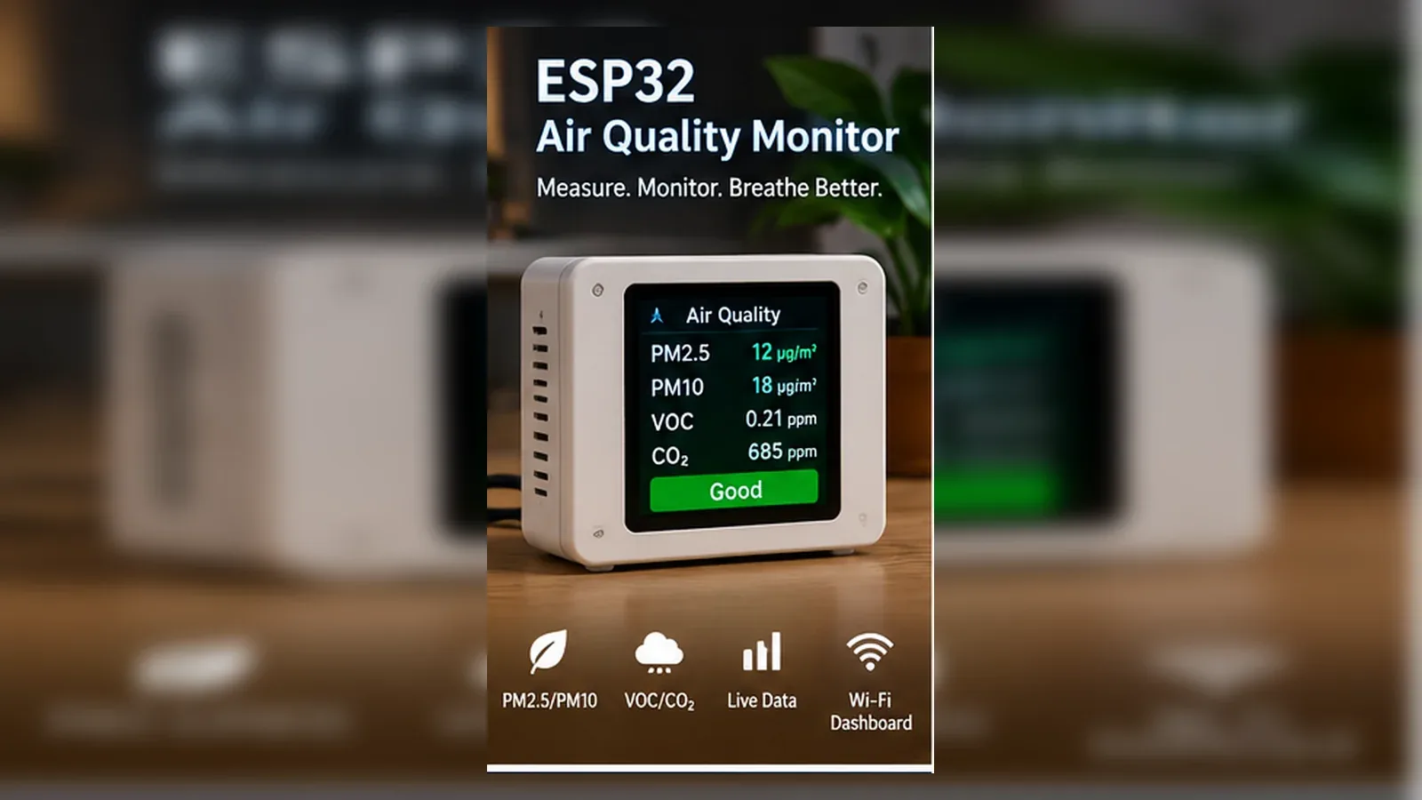
Build an Indoor Air Quality Monitor
The Story
ESP32 Air Quality Monitor solves a real beginner problem: turning an ESP32 reading into a useful physical or networked result. Build this to learn slow analog sensors, warm-up behavior, threshold tuning, and why gas sensor projects need calibration before automation.
The tutorial focuses on the engineering path: prove the input, understand the circuit, write readable code, then test the output under real conditions.
Explain Like I'm 12
The MQ135 behaves like a smoke-sensitive nose that needs time to wake up. The ESP32 watches how the reading changes, then reacts only after you decide what counts as normal for your room.
Safety Standards
- Unplug USB before changing jumper wires. Recheck 3.3 V, 5 V, and GND before reconnecting power.
- Do not power motors, pumps, LED strips, or servos from the ESP32 3.3 V pin. Use a suitable external supply and common ground.
- Breadboards are for low-current prototypes. Move high-current or unattended builds to proper terminals, enclosure, strain relief, and fusing.
- Relay and mains-voltage projects require isolation, correct relay ratings, enclosed wiring, and qualified adult supervision.
- Motors and servos can reset the ESP32 when they draw surge current. Use a separate motor supply, driver module, and flyback protection where needed.
What You Will Build
An ESP32 monitor that reads an MQ135 gas sensor, prints live raw values, and drives an alert output or fan relay when air quality crosses a tested threshold.
Learning Objectives
- Read a gas sensor as an analog input.
- Create a fresh-air baseline before choosing an alert threshold.
- Drive a relay or fan control signal safely from an ESP32 GPIO.
- Understand why gas sensors need warm-up and calibration.
- Separate trend monitoring from precise air-quality measurement.
Components List
- ESP32 Dev BoardRequired for this build
- Mq135 Gas SensorRequired for this build
- Fan RelayRequired for this build
- 5V Power SupplyRequired for this build
- Breadboard and jumper wiresFor safe low-voltage prototyping
- USB data cableProgramming and bench power
Bill of Materials
| Part | Qty | Estimated Cost | Notes |
|---|---|---|---|
| ESP32 Dev Board | 1 | Varies | Required for this build |
| Mq135 Gas Sensor | 1 | Varies | Required for this build |
| Fan Relay | 1 | Varies | Required for this build |
| 5V Power Supply | 1 | Varies | Required for this build |
| Breadboard and jumper wires | 1 set | Varies | For safe low-voltage prototyping |
Wiring
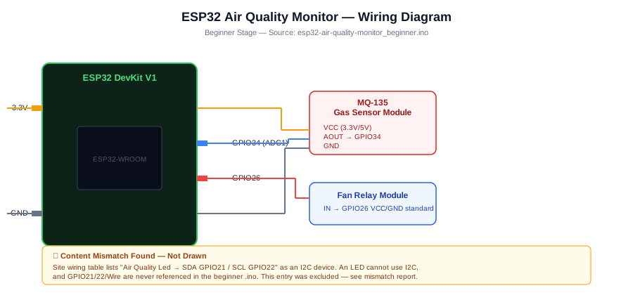
Power the MQ135, wait for warm-up, record a fresh-air baseline on GPIO34, then connect the GPIO26 fan or relay input only after the raw readings behave consistently. The module output is useful for trend and threshold practice, not calibrated ppm measurement.
-
1
Unplug USB before changing wires.
-
2
Connect Mq135 Gas Sensor signal to GPIO34.
-
3
Connect Fan Relay control to GPIO26.
-
4
Connect VCC to 3.3V/5V.
-
5
Connect GND to GND.
-
6
Reconnect USB, upload the sketch, and open Serial Monitor at 115200 baud unless the code says otherwise.
GPIO Mapping
| Signal | ESP32 Pin | Direction | Notes |
|---|---|---|---|
| Mq135 Gas Sensor signal | GPIO34 | Input | Match this wire to the code constant. |
| Fan Relay control | GPIO26 | Output | Match this wire to the code constant. |
| VCC | 3.3V/5V | Power | Match this wire to the code constant. |
| GND | GND | Ground | Match this wire to the code constant. |
Circuit Explanation
The MQ135 module changes its analog output as gas concentration changes near the heated sensing element. The ESP32 reads that voltage on an ADC pin. The relay or fan input is controlled from a GPIO pin, but the fan power must come from a suitable external supply or relay module, not directly from the ESP32 pin.
Engineering Explanation
Low-cost MQ gas modules are useful for trend detection, not laboratory-grade air measurement. They need warm-up time, stable power, fresh-air baseline readings, and threshold testing in the actual room. Treat the raw number as a relative indicator unless you have calibrated equipment and a known sensor curve.
Libraries
- Arduino ESP32 coreInstall ESP32 board support in Arduino IDE.
Code
Copy into Arduino IDE. Install any libraries noted in the component guides first.
// ESP32 Air Quality Monitor for Indoor Air
const int SENSOR_PIN = 34;
const int OUTPUT_PIN = 26;
const int THRESHOLD = 1813;
const int SAMPLE_DELAY_MS = 300;

void setup() {
  Serial.begin(115200);
  pinMode(OUTPUT_PIN, OUTPUT);
  pinMode(SENSOR_PIN, INPUT);
  Serial.println("Starting: air quality monitor for indoor air");
  Serial.print("Threshold: ");
  Serial.println(THRESHOLD);
}

void loop() {
  int reading = analogRead(SENSOR_PIN);
  Serial.print("Mq135 Gas Sensor signal: ");
  Serial.println(reading);
  bool active = reading < THRESHOLD;
  digitalWrite(OUTPUT_PIN, active ? HIGH : LOW);
  delay(SAMPLE_DELAY_MS);
}
Code Explanation
The sketch reads the MQ135 analog output on GPIO34 every 300 ms, prints the raw ADC value, compares it with THRESHOLD, and drives GPIO26 for a low-voltage fan or relay input. The threshold is a classroom test value, not a calibrated ppm limit.
Expected Output
Serial Monitor prints "Starting: air quality monitor for indoor air", the threshold, and repeated "Mq135 Gas Sensor signal" raw ADC values. GPIO26 changes only when the reading crosses the tested threshold.
Build Photos
- Breadboard overviewShow ESP32, module, output device, and power rails.
- Close-up wiringShow signal pins clearly enough for learners to compare.
- Working outputShow Serial Monitor, LEDs, display, or dashboard after the condition changes.
Troubleshooting
- Sensor value never changes Wait several minutes for warm-up, confirm VCC/GND, and print raw analog values before threshold logic.
- Relay chatters on and off Add hysteresis or require several bad readings before turning the fan on.
- ESP32 resets when the fan starts Use a separate power supply for the fan and relay module, and add proper flyback protection if using an inductive load.
- Values are high all the time Move the sensor away from solder fumes, cleaners, smoke, or direct airflow and create a new baseline.
Common Mistakes
- Expecting accurate ppm values from an uncalibrated MQ135 module.
- Powering a fan or relay coil directly from an ESP32 GPIO.
- Testing the sensor immediately after power-up before the heater stabilizes.
- Forgetting common ground between ESP32 and the relay module.
- Using GPIO34 as an output; it is input-only.
Testing Checklist
- Upload a simple Blink sketch first to confirm the board and USB cable work.
- Power the MQ135 and wait for warm-up before judging readings.
- Connect the GPIO34 signal and record a fresh-air baseline in Serial Monitor.
- Adjust THRESHOLD from your own baseline before connecting a fan or relay.
- Connect the GPIO26 output only after the raw readings look believable.
- Power-cycle the project and confirm it starts in a safe state.
Engineering Tips
- Use the raw ADC number until you have a real calibration method.
- Keep the sensor away from the ESP32 regulator heat.
- Add hysteresis so the fan does not rapidly toggle near the threshold.
- Never connect mains-powered fans directly on a breadboard.
- Log baseline values at different times of day before deciding thresholds.
Performance Tips
- Sample slowly because MQ sensors respond slowly.
- Use moving averages for smoother decisions.
- Turn Wi-Fi publishing into a timed task instead of blocking sensor reads.
- Use local threshold control if the network is unavailable.
Upgrade Ideas
- Publish readings to an MQTT broker or Home Assistant
- Add an OLED display that shows raw air trend and fan state.
Real-World Applications
- Classroom air trend indicator
- Workshop fume awareness
- Smart ventilation prototype
- Home Assistant environmental node
Downloads
- ESP32 Air Quality Monitor Arduino sketchUse the code section as the source sketch.
- Bench test checklistFollow the testing checklist before permanent installation.
FAQs
Does the MQ135 sensor need warm-up time?
Yes. The project troubleshooting already expects the raw value to settle after power-up, so wait several minutes before judging thresholds or turning the relay/fan logic on.
Can this monitor identify every harmful gas?
No. This build uses a simple MQ135 analog threshold, so treat it as an educational air-quality indicator, not as a certified safety monitor or gas detector.
Where should I place the sensor while testing?
Keep it away from solder fumes, cleaners, smoke, and direct fan airflow while you create a baseline. Those conditions can make the reading look high all the time.
Review, Testing, and References
Author: Abdul Mubeen and the ESP32 Engine editorial team. Last updated: 2026-08-26. Reviewed: wiring logic, Arduino code structure, beginner safety, and learning sequence.
Educational level: Beginner. Estimated completion time: 75-100 min. This project is for learning and prototyping; production or unattended hardware needs additional engineering review.
Project Complete!
You completed ESP32 Air Quality Monitor as a real ESP32 engineering build, not just a wiring demo. You now know how to test the input, protect the circuit, explain the code, and improve the project safely.
- Read and verify project input hardware
- Map signals to safe ESP32 GPIO pins
- Debug with Serial Monitor
- Apply safety and performance checks
- Plan the next learning step