
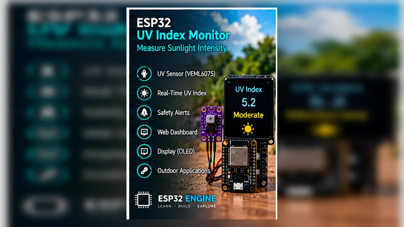
Build an Estimated UV Index Monitor
The Story
The repository already references VEML6075, so this page keeps one sensor choice and labels every UV value as an estimate.
Explain Like I'm 12
The UV sensor notices ultraviolet light. The ESP32 turns that into an estimated number and a category, but real sun-safety decisions still come from official guidance.
Learning Support
- Recommended ageAges 12+
- Adult supervisionAdult review recommended for outdoor testing and health-guidance boundaries.
- Classroom usePair with a science lesson on UV bands and official public-health scales.
- Parent promptAsk why a hobby sensor should be compared with official forecasts instead of replacing them.
- Screen-free activityLook up official UV-index bands and write them down before coding the categories.
- Next challengeAdd a rolling average over several minutes to smooth noisy estimates.
- Skills practiced
- I2C sensor wiring
- UV band categorization
- OLED display
- Estimate labeling
- Learning outcomes
- Wire VEML6075 on GPIO21/GPIO22.
- Display Estimated UV Index values.
- Map estimates into public UV-index bands.
- Explain glass, shade, and calibration limits.
- Mini experiments
- Compare indoors, near a window, and brief outdoor readings.
- Partially shade the sensor.
- Log estimated readings at different times of day.
Safety Standards
- Unplug USB before changing jumper wires. Recheck 3.3 V, 5 V, and GND before reconnecting power.
- Do not power motors, pumps, LED strips, or servos from the ESP32 3.3 V pin. Use a suitable external supply and common ground.
- Breadboards are for low-current prototypes. Move high-current or unattended builds to proper terminals, enclosure, strain relief, and fusing.
What You Will Build
An educational estimated UV-index monitor using the VEML6075 sensor and optional OLED display.
Learning Objectives
- Wire VEML6075 on GPIO21/GPIO22.
- Display Estimated UV Index values.
- Map estimates into public UV-index bands.
- Explain glass, shade, and calibration limits.
Components List
- ESP32 DevKit boardMain 3.3 V logic controller.
- VEML6075 UVA/UVB sensor moduleI2C UV sensor; use 3.3 V logic.
- SSD1306 OLED displayOptional I2C display on GPIO21/GPIO22.
- Breadboard and jumper wiresFor low-voltage I2C wiring.
Bill of Materials
| Part | Qty | Estimated Cost | Notes |
|---|---|---|---|
| ESP32 DevKit board | 1 | Varies | Main 3.3 V logic controller. |
| VEML6075 UVA/UVB sensor module | 1 | Varies | I2C UV sensor; use 3.3 V logic. |
| SSD1306 OLED display | 1 | Varies | Optional I2C display on GPIO21/GPIO22. |
| Breadboard and jumper wires | 1 | Varies | For low-voltage I2C wiring. |
Wiring
VEML6075 and OLED share I2C: SDA GPIO21 and SCL GPIO22. Power the sensor from 3.3 V unless your breakout documentation says otherwise.
-
1
Unplug USB before wiring.
-
2
Connect VEML6075 VCC to 3.3 V and GND to GND.
-
3
Connect VEML6075 SDA to GPIO21 and SCL to GPIO22.
-
4
Connect OLED SDA/SCL to the same GPIO21/GPIO22 bus if used.
-
5
Keep the sensor window unobstructed.
-
6
Upload the sketch and check that Serial output says Estimated UV Index.
GPIO Mapping
| Signal | ESP32 Pin | Direction | Notes |
|---|---|---|---|
| VEML6075 SDA | GPIO21 | I2C data | Shared with OLED if present. |
| VEML6075 SCL | GPIO22 | I2C clock | Shared with OLED if present. |
| OLED SDA/SCL | GPIO21/GPIO22 | I2C | Optional display. |
Circuit Explanation
The VEML6075 reports UVA/UVB-related readings over I2C. The code reads the library's UVI estimate and labels it as an estimate.
Engineering Explanation
Glass, shade, sensor angle, and breakout calibration affect estimates. UV-index bands are public categories, not proof of medical accuracy.
Libraries
- Adafruit VEML6075Install from Arduino Library Manager.
- Adafruit SSD1306For optional OLED display.
Code
Copy into Arduino IDE. Install any libraries noted in the component guides first.
// ESP32 VEML6075 estimated UV index monitor
// Educational estimate only; follow official weather and health guidance.
#include <Wire.h>
#include <Adafruit_SSD1306.h>
#include <Adafruit_VEML6075.h>

Adafruit_VEML6075 uv = Adafruit_VEML6075();
Adafruit_SSD1306 oled(128, 64, &Wire, -1);

const char *uvBand(float estimatedUv) {
  if (estimatedUv < 3.0) return "Low estimate";
  if (estimatedUv < 6.0) return "Moderate estimate";
  if (estimatedUv < 8.0) return "High estimate";
  if (estimatedUv < 11.0) return "Very high estimate";
  return "Extreme estimate";
}

void setup() {
  Serial.begin(115200);
  Wire.begin(21, 22);
  oled.begin(SSD1306_SWITCHCAPVCC, 0x3C);
  oled.setTextColor(WHITE);

  if (!uv.begin()) {
    Serial.println("VEML6075 not found. Check 3.3 V, SDA GPIO21, and SCL GPIO22.");
    while (true) delay(10);
  }
  Serial.println("Estimated UV Index monitor ready. Educational use only.");
}

void loop() {
  float uva = uv.readUVA();
  float uvb = uv.readUVB();
  float estimatedUv = uv.readUVI();
  const char *band = uvBand(estimatedUv);

  Serial.printf("Estimated UV Index: %.1f  Band: %s  UVA raw: %.1f  UVB raw: %.1f\n",
                estimatedUv, band, uva, uvb);

  oled.clearDisplay();
  oled.setCursor(0, 0);
  oled.setTextSize(1);
  oled.println("Estimated UV Index");
  oled.setTextSize(2);
  oled.println(estimatedUv, 1);
  oled.setTextSize(1);
  oled.println(band);
  oled.println("Educational estimate");
  oled.display();

  delay(5000);
}
Code Explanation
The loop reads raw UVA/UVB and estimated UVI, classifies the estimated value into standard UV-index bands, and displays the estimate.
Expected Output
Serial and OLED both say Estimated UV Index. Indoor readings may be near zero, especially through glass.
Troubleshooting
- Sensor not found Check 3.3 V, SDA GPIO21, SCL GPIO22, and I2C address conflicts.
- Estimated reading near zero indoors That is expected in many indoor conditions and through glass.
- Outdoor estimates jump Check sensor angle, shadow, and obstruction.
Common Mistakes
- Writing UV Index without Estimated.
- Giving medical exposure advice.
- Using a different sensor in the text than in code.
- Treating indoor zero readings as a wiring fault.
Testing Checklist
- Confirm I2C detection.
- Compare indoor and near-window estimates.
- Briefly compare outdoor estimates while following normal safety guidance.
Engineering Tips
- Keep the word Estimated with every value.
- Use official forecasts for decisions.
- Avoid touching or covering the sensor window.
Upgrade Ideas
- Add rolling average.
- Add local CSV logging.
- Add a display-only daily trend chart without medical advice.
Real-World Applications
- UV sensor education
- I2C environmental demo
- Public scale categorization lesson
FAQs
Can I use this for health decisions?
No. It is an educational estimate only.
Why does glass affect readings?
Window glass can block significant UV, especially UVB.
Can it tell me how long to stay in the sun?
No. Use official local health and weather guidance.
Review, Testing, and References
Author: Abdul Mubeen and the ESP32 Engine editorial team. Last updated: 2026-06-27. Reviewed: wiring logic, Arduino code structure, beginner safety, and learning sequence.
Educational level: Beginner. Estimated completion time: 60-75 min. This project is for learning and prototyping; production or unattended hardware needs additional engineering review.
Project Complete!
You completed ESP32 UV Index Monitor (Educational Estimate) with matching wiring, code, tests, and limitations.
- I2C sensor wiring
- UV band categorization
- OLED display