
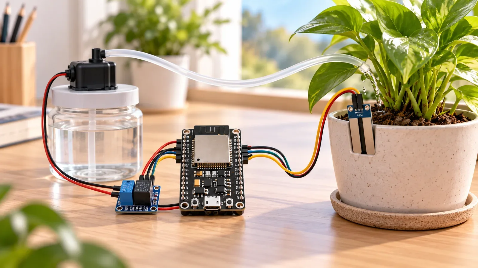
Build Your Smart Irrigation System
The Story
ESP32 Smart Irrigation System turns the ESP32 into a real object that senses something, decides what it means, and reacts in the physical world.
The important lesson is not only the finished irrigation controller. You learn how to separate input, decision logic, and output so a project stays debuggable instead of becoming a pile of wires and guesses.
Explain Like I'm 12
Think of the ESP32 as the brain. The soil moisture probe is how it notices the world. The relay-controlled pump is how it answers back. The code is the rule book that tells the brain what to do when the numbers change.
Safety Standards
- Unplug USB before changing jumper wires. Recheck 3.3 V, 5 V, and GND before reconnecting power.
- Do not power motors, pumps, LED strips, or servos from the ESP32 3.3 V pin. Use a suitable external supply and common ground.
- Breadboards are for low-current prototypes. Move high-current or unattended builds to proper terminals, enclosure, strain relief, and fusing.
- Relay and mains-voltage projects require isolation, correct relay ratings, enclosed wiring, and qualified adult supervision.
What You Will Build
A working irrigation controller with an ESP32, a real input, a controlled output, Serial Monitor diagnostics, and a wiring map you can expand into a more advanced version.
Learning Objectives
- Wire and test the soil moisture probe before connecting the rest of the circuit.
- Map each signal to a named ESP32 GPIO and keep the code constants readable.
- Control relay-controlled pump using a clear threshold or command instead of hidden magic numbers.
- Use Serial Monitor as an engineering tool, not only as a success message.
- Identify power, wiring, and timing faults using a repeatable test checklist.
Components List
- ESP32 DevKit boardMain controller
- Soil Moisture ProbePrimary input for the project
- Relay-Controlled PumpPhysical output controlled by ESP32
- Breadboard and jumper wiresPrototype wiring
- USB data cableProgramming and testing
Bill of Materials
| Part | Qty | Estimated Cost | Notes |
|---|---|---|---|
| ESP32 DevKit | 1 | $6-$10 | USB board |
| Soil Moisture Probe | 1 | $2-$10 | Project input |
| Relay-Controlled Pump | 1 | $3-$12 | Use low-voltage test hardware |
| Breadboard and wires | 1 set | $3-$5 | Prototype wiring |
Wiring
Wire the soil moisture probe first, verify readings, then connect the relay-controlled pump.
-
1
Unplug USB before placing modules on the breadboard.
-
2
Connect the soil moisture probe power pins to the correct 3.3 V or 5 V rail according to its module label.
-
3
Connect the soil moisture probe signal line to GPIO34.
-
4
Connect the relay-controlled pump control input to GPIO26 and share ground with the ESP32.
-
5
Power the ESP32 from USB and test the input reading before enabling the output.
GPIO Mapping
| Signal | ESP32 Pin | Direction | Notes |
|---|---|---|---|
| soil moisture probe | GPIO34 | Input | Read before controlling output |
| relay-controlled pump | GPIO26 | Output | Drive through a module or driver |
| Status LED | GPIO2 | Output | Optional debug indicator |
| Serial Monitor | USB | Debug | 115200 baud |
Circuit Explanation
The circuit is split into an input side and an output side. The soil moisture probe tells the ESP32 what is happening. The relay-controlled pump receives a controlled signal from the ESP32, usually through a driver, relay, or module that can handle more current than a GPIO pin.
Engineering Explanation
A reliable irrigation controller is built in layers. First prove the input, then prove the output, then join them with simple state logic. This prevents a common beginner problem where the robot, lock, or automation fails and every wire looks suspicious at the same time.
Code
Copy into Arduino IDE. Install any libraries noted in the component guides first.
const int SOIL_PIN = 34;
const int RELAY_PIN = 26;

const int DRY_ON = 2600;
const int WET_OFF = 1900;
bool pumpOn = false;

void setup() {
  Serial.begin(115200);
  pinMode(RELAY_PIN, OUTPUT);
  digitalWrite(RELAY_PIN, LOW);
  Serial.println("Smart irrigation ready");
}

void loop() {
  int soil = analogRead(SOIL_PIN);
  if (!pumpOn && soil > DRY_ON) pumpOn = true;
  if (pumpOn && soil < WET_OFF) pumpOn = false;

  digitalWrite(RELAY_PIN, pumpOn ? HIGH : LOW);
  Serial.print("Soil raw: "); Serial.print(soil);
  Serial.print(" | Pump: "); Serial.println(pumpOn ? "ON" : "OFF");
  delay(1000);
}
Code Explanation
The example uses named pins, reads the input, converts the reading into a true or false decision, and then updates the output and status LED. Replace the threshold with values measured from your own soil moisture probe because modules vary.
Expected Output
Serial Monitor should show a changing reading. When the soil moisture probe reaches the test condition, the status LED and relay-controlled pump should switch state. If the reading changes but the output does not, debug the output wiring separately.
Build Photos
- Breadboard overviewShow the ESP32, module placement, and power rails clearly.
- Close-up wiringCapture each GPIO wire so beginners can compare their build.
- Working outputShow the Serial Monitor, display, robot, pump, or lock state after the code runs.
Troubleshooting
- soil moisture probe never changes Check power, ground, signal pin, and whether the sensor is analog or digital.
- relay-controlled pump does not switch Test the output module with a simple blink-style sketch before using the full project.
- ESP32 resets under load Use a separate supply for motors, pumps, or locks and keep only control signals connected to ESP32.
- Behavior is reversed Your module may be active LOW; invert the output logic after confirming with Serial Monitor.
Common Mistakes
- Testing input and output for the first time together.
- Using a GPIO pin that does not match the code constant.
- Expecting an ESP32 GPIO to power a motor, pump, or lock directly.
- Forgetting the shared ground between modules.
Testing Checklist
- ESP32 appears on the correct port and accepts a basic blink upload.
- Ground is shared between every module that exchanges signals with the ESP32.
- Each GPIO in the code matches the wire connected on the breadboard.
- Serial Monitor prints startup text at 115200 baud.
- The soil moisture probe value changes when you create a real test condition.
- The relay-controlled pump changes only when the expected condition is reached.
- The circuit still behaves correctly after power is removed and restored.
Upgrade Ideas
- Add OLED status feedback.
- Add Wi-Fi dashboard or mobile alerts.
- Store event history in flash or a cloud service.
- Add calibration settings instead of hard-coded thresholds.
Real-World Applications
- Classroom irrigation controller trainer
- STEM lab demonstration
- Home automation prototype
- Engineering debugging practice
- IoT portfolio project
Downloads
- ESP32 Smart Irrigation System Arduino sketchUse the code section as the downloadable source until file downloads are published.
- Wiring checklistMatch the GPIO table and wiring steps before powering the circuit.
- Troubleshooting worksheetRecord symptoms, Serial output, voltage checks, and fixes.
FAQs
Why does my soil moisture probe reading look wrong?
Soil type, sensor depth, and probe condition change the reading. Calibrate the GPIO34 value in dry and wet soil before trusting pump decisions.
Why does relay-controlled pump not respond?
Check the ground connection first. Then confirm the output pin, power supply capacity, and whether the output module uses active HIGH or active LOW logic.
Can the pump run directly from an ESP32 pin?
No. The ESP32 should only drive the relay or driver input. Power the pump from a suitable separate supply and keep a common ground where the driver requires it.
Review, Testing, and References
Author: Abdul Mubeen and the ESP32 Engine editorial team. Last updated: 2026-06-29. Reviewed: wiring logic, Arduino code structure, beginner safety, and learning sequence.
Educational level: Beginner. Estimated completion time: 90-150 min. This project is for learning and prototyping; production or unattended hardware needs additional engineering review.
Project Complete!
You built a real irrigation controller and learned how to connect sensing, decision logic, and output control in one ESP32 project.
- Wire and test soil moisture probe
- Control relay-controlled pump from ESP32
- Debug hardware with Serial Monitor
- Improve the project safely