
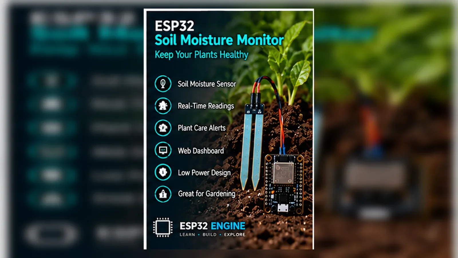
Build a Soil Moisture Monitor
The Story
ESP32 Soil Moisture Monitor solves a real beginner problem: turning an ESP32 reading into a useful physical or networked result. Build this if you want to understand analog sensors, calibration, and threshold logic before moving to automatic irrigation.
The tutorial focuses on the engineering path: prove the input, understand the circuit, write readable code, then test the output under real conditions.
Explain Like I'm 12
The ESP32 is a plant caretaker with a moisture meter. The sensor gives a changing number, the code decides whether that number means wet or dry, and the LEDs explain the decision.
Safety Standards
- Unplug USB before changing jumper wires. Recheck 3.3 V, 5 V, and GND before reconnecting power.
- Do not power motors, pumps, LED strips, or servos from the ESP32 3.3 V pin. Use a suitable external supply and common ground.
- Breadboards are for low-current prototypes. Move high-current or unattended builds to proper terminals, enclosure, strain relief, and fusing.
- Relay and mains-voltage projects require isolation, correct relay ratings, enclosed wiring, and qualified adult supervision.
What You Will Build
A plant monitor that reads a capacitive soil sensor, converts raw ADC values into a moisture percentage, and uses LEDs or a buzzer to show when watering is needed.
Learning Objectives
- Read an analog soil moisture sensor with an ESP32 ADC pin.
- Calibrate dry and wet readings for your own sensor and soil.
- Convert raw ADC values into a useful percentage.
- Use LEDs or a buzzer as clear status outputs.
- Recognize why capacitive sensors are better than resistive probes for long-term plant projects.
Components List
- 1× ESP32 DevKit V1Required for this build
- 1× Capacitive Soil Moisture Sensor v1.2NOT the resistive (fork) type — those corrode
- 1× LED (green) + 220 Ω resistorMoist indicator
- 1× LED (yellow) + 220 Ω resistorDry warning
- 1× LED (red) + 220 Ω resistorCritical dry alert
- 1× Active Buzzer (5 V)Optional alert sound
- 1× Breadboard + jumper wiresRequired for this build
- USB data cableProgramming and bench power
Bill of Materials
| Part | Qty | Estimated Cost | Notes |
|---|---|---|---|
| 1× ESP32 DevKit V1 | 1 | Varies | Required for this build |
| 1× Capacitive Soil Moisture Sensor v1.2 | 1 | Varies | NOT the resistive (fork) type — those corrode |
| 1× LED (green) + 220 Ω resistor | 1 | Varies | Moist indicator |
| 1× LED (yellow) + 220 Ω resistor | 1 | Varies | Dry warning |
| 1× LED (red) + 220 Ω resistor | 1 | Varies | Critical dry alert |
| 1× Active Buzzer (5 V) | 1 | Varies | Optional alert sound |
Wiring
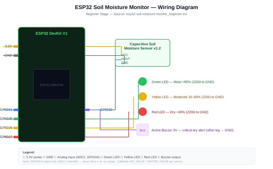
Wire the capacitive probe to GPIO34 first, print raw ADC values, and calibrate dry/wet readings before trusting the LED or buzzer thresholds.
-
1
Unplug USB before changing wires.
-
2
Connect Sensor AOUT to GPIO 34 (ADC1 channel — input only, do not drive HIGH).
-
3
Connect Sensor VCC to 3.3 V (Some sensors accept 3.3–5 V; check your module).
-
4
Connect Sensor GND to GND.
-
5
Connect Green LED (+ 220 Ω) to GPIO 25 (Moist (> 60%)).
-
6
Connect Yellow LED (+ 220 Ω) to GPIO 26 (Moderate (30–60%)).
-
7
Connect Red LED (+ 220 Ω) to GPIO 27 (Dry (< 30%)).
-
8
Connect Buzzer + to GPIO 32 (Only sounds when critically dry).
-
9
Reconnect USB, upload the sketch, and open Serial Monitor at 115200 baud unless the code says otherwise.
GPIO Mapping
| Signal | ESP32 Pin | Direction | Notes |
|---|---|---|---|
| Sensor AOUT | GPIO 34 | Input | ADC1 channel — input only, do not drive HIGH |
| Sensor VCC | 3.3 V | Power | Some sensors accept 3.3–5 V; check your module |
| Sensor GND | GND | Ground | Match this wire to the code constant. |
| Green LED (+ 220 Ω) | GPIO 25 | Output | Moist (> 60%) |
| Yellow LED (+ 220 Ω) | GPIO 26 | Output | Moderate (30–60%) |
| Red LED (+ 220 Ω) | GPIO 27 | Output | Dry (< 30%) |
| Buzzer + | GPIO 32 | Output | Only sounds when critically dry |
Circuit Explanation
The capacitive probe produces an analog voltage that changes with the moisture around the sensor. GPIO34 is an ADC input, so it can read voltage but cannot drive an output. LEDs use separate GPIO pins through resistors so the ESP32 only supplies safe indicator current. The buzzer is optional and should be tested after the moisture reading works.
Engineering Explanation
Soil moisture sensors are not absolute instruments. Soil type, sensor depth, salt content, and temperature all change the raw ADC reading. A reliable monitor is calibrated in your own dry and wet conditions, averages several samples, and uses thresholds that are tested with real soil instead of copied from another build.
Libraries
- Arduino ESP32 coreInstall ESP32 board support in Arduino IDE.
Code
Copy into Arduino IDE. Install any libraries noted in the component guides first.
/*
 * ESP32 Soil Moisture Monitor — Beginner
 * Reads capacitive soil sensor, maps to percentage, lights LEDs.
 *
 * CALIBRATION REQUIRED:
 *   1) Place sensor in dry air → note AIR_VALUE (should be ~2800–3200)
 *   2) Submerge sensor tip in water → note WATER_VALUE (should be ~1200–1500)
 *   Update the defines below with your sensor's actual values.
 */
#define SENSOR_PIN  34
#define LED_GREEN   25   // Moist
#define LED_YELLOW  26   // Moderate
#define LED_RED     27   // Dry
#define BUZZER      32

// ── CALIBRATE THESE for your sensor ─────────────────────────────
#define AIR_VALUE   2800  // ADC reading in dry air (0% moisture)
#define WATER_VALUE 1200  // ADC reading fully in water (100% moisture)
// ────────────────────────────────────────────────────────────────

int readMoisturePercent() {
  // Average 10 readings to reduce ADC noise on ESP32
  long sum = 0;
  for (int i = 0; i < 10; i++) { sum += analogRead(SENSOR_PIN); delay(5); }
  int raw = sum / 10;
  int pct = map(raw, AIR_VALUE, WATER_VALUE, 0, 100);
  return constrain(pct, 0, 100);
}

void setup() {
  Serial.begin(115200);
  analogReadResolution(12);   // 12-bit ADC: 0–4095
  pinMode(LED_GREEN,  OUTPUT);
  pinMode(LED_YELLOW, OUTPUT);
  pinMode(LED_RED,    OUTPUT);
  pinMode(BUZZER,     OUTPUT);
  Serial.println("Soil Moisture Monitor started.");
  Serial.printf("Calibration: AIR=%d, WATER=%dn", AIR_VALUE, WATER_VALUE);
}

void loop() {
  int pct = readMoisturePercent();
  Serial.printf("Moisture: %d%%n", pct);

  // Turn all LEDs off first
  digitalWrite(LED_GREEN,  LOW);
  digitalWrite(LED_YELLOW, LOW);
  digitalWrite(LED_RED,    LOW);
  digitalWrite(BUZZER,     LOW);

  if (pct >= 60) {
    digitalWrite(LED_GREEN, HIGH);
    Serial.println("Status: Moist — plant is happy");
  } else if (pct >= 30) {
    digitalWrite(LED_YELLOW, HIGH);
    Serial.println("Status: Moderate — consider watering soon");
  } else {
    digitalWrite(LED_RED, HIGH);
    // Pulse buzzer 3 times for critical alert
    for (int i = 0; i < 3; i++) {
      digitalWrite(BUZZER, HIGH); delay(200);
      digitalWrite(BUZZER, LOW);  delay(200);
    }
    Serial.println("Status: DRY — water the plant now!");
  }

  delay(10000);   // Read every 10 seconds
}
Code Explanation
The sketch averages 10 ADC readings from GPIO34, maps the raw value between AIR_VALUE and WATER_VALUE, constrains the result to 0-100 percent, and then lights green, yellow, or red LEDs. The buzzer only pulses in the dry branch.
Expected Output
Serial Monitor prints the calibration values and repeated "Moisture: NN%" lines. Green indicates moist soil, yellow indicates moderate moisture, and red plus buzzer means the calibrated reading is dry.
Troubleshooting
- Moisture is always 0 percent or 100 percent Print the raw ADC value first. Update AIR_VALUE and WATER_VALUE with readings from your own dry air and wet test.
- Readings jump while the sensor is not moving Average multiple samples, keep wires short, and keep the sensor lead away from motors, pumps, and Wi-Fi antennas.
- LED status looks backwards Check whether your calibration has AIR_VALUE greater than WATER_VALUE. Many capacitive modules output lower voltage when wetter.
- Buzzer sounds too often Raise the dry threshold or require several dry readings in a row before sounding the buzzer.
Common Mistakes
- Using a resistive fork-style sensor for a long-term outdoor build; those probes corrode quickly.
- Copying calibration values without measuring your own dry and wet readings.
- Driving an LED without a current-limiting resistor.
- Assuming 0 percent and 100 percent readings will be identical across soil types.
- Reading the sensor while Wi-Fi is active and then wondering why ADC values are noisier.
Testing Checklist
- Upload a simple Blink sketch first to confirm the board and USB cable work.
- Wire only the sensor first and print raw GPIO34 readings.
- Record dry-air and wet-test readings, then update AIR_VALUE and WATER_VALUE.
- Add LEDs with 220 ohm resistors only after the percentage makes sense.
- Add the buzzer last and confirm it sounds only for dry readings.
- Power-cycle the project and confirm it starts in a safe state.
Engineering Tips
- Use GPIO34, GPIO35, GPIO36, or GPIO39 for analog-only sensor inputs.
- Record raw ADC values before writing percentage logic.
- Keep the sensor electronics above the soil; only the probe area should enter the soil.
- If you add a pump later, power it from a separate supply and share ground only where the driver requires it.
- Label dry, damp, and wet readings in a notebook before choosing thresholds.
Performance Tips
- Average 10-20 readings to reduce ADC noise.
- Read every few seconds or minutes; soil changes slowly.
- Power the sensor only while reading if you need lower corrosion and lower battery use.
- Use deep sleep for battery plant monitors.
Upgrade Ideas
- Add multiple sensors on GPIO 35, 36 for multi-plant monitoring with individual alerts
- Record daily readings to detect drying trends before plants become stressed
Real-World Applications
- Indoor plant monitoring
- Greenhouse seedling trays
- School experiments about soil and water retention
- Starter project for smart irrigation
Downloads
- ESP32 Soil Moisture Monitor Arduino sketchUse the code section as the source sketch.
- Bench test checklistFollow the testing checklist before permanent installation.
FAQs
Why should I avoid resistive probes for long-term soil monitoring?
Resistive fork probes corrode quickly in wet soil. This project uses a capacitive soil moisture sensor because it is better suited to repeated learning tests.
How do I calibrate dry and wet values?
Print the raw GPIO34 reading in dry air and in wet soil, then set thresholds between your measured values. Do not copy another plant's calibration numbers.
Can one threshold work for every soil type?
No. Soil mix, pot size, sensor depth, and watering pattern change the reading, so calibrate for the plant and placement you are actually using.
Review, Testing, and References
Author: Abdul Mubeen and the ESP32 Engine editorial team. Last updated: 2026-08-26. Reviewed: wiring logic, Arduino code structure, beginner safety, and learning sequence.
Educational level: Beginner. Estimated completion time: 60-90 min. This project is for learning and prototyping; production or unattended hardware needs additional engineering review.
Project Complete!
You completed ESP32 Soil Moisture Monitor as a real ESP32 engineering build, not just a wiring demo. You now know how to test the input, protect the circuit, explain the code, and improve the project safely.
- Read and verify project input hardware
- Map signals to safe ESP32 GPIO pins
- Debug with Serial Monitor
- Apply safety and performance checks
- Plan the next learning step