
Build an ESP32-CAM QR Scanner
The Story
ESP32-CAM QR Code Scanner solves a real beginner problem: turning an ESP32 reading into a useful physical or networked result. Build this after the basic camera server because QR scanning adds focus, lighting, decoding, and serial debugging challenges.
The tutorial focuses on the engineering path: prove the input, understand the circuit, write readable code, then test the output under real conditions.
Explain Like I'm 12
A QR scanner is a camera plus a translator. The camera sees a square pattern, and the decoding library turns that pattern into text the ESP32 can use.
Safety Standards
- Unplug USB before changing jumper wires. Recheck 3.3 V, 5 V, and GND before reconnecting power.
- Do not power motors, pumps, LED strips, or servos from the ESP32 3.3 V pin. Use a suitable external supply and common ground.
- Breadboards are for low-current prototypes. Move high-current or unattended builds to proper terminals, enclosure, strain relief, and fusing.
- Relay and mains-voltage projects require isolation, correct relay ratings, enclosed wiring, and qualified adult supervision.
What You Will Build
An ESP32-CAM scanner that captures grayscale frames from the onboard OV2640 camera and decodes QR payloads on the ESP32 with Quirc. The beginner build prints decoded text to Serial before any lock, relay, web page, or network validation is added.
Learning Objectives
- Program and boot an ESP32-CAM correctly.
- Capture frames suitable for QR decoding.
- Understand why lighting and focus affect recognition.
- Print decoded text to Serial Monitor.
- Plan safe next steps for access or inventory projects.
Components List
- 1× ESP32-CAM module (AI-Thinker)OV2640 camera
- 1× FTDI USB-to-serial adapterProgramming and Serial Monitor
- 1× 5 V 2 A power supplyRequired for this build
- 1× Printed QR code or phone screenFor testing
- Breadboard and jumper wiresFor safe low-voltage prototyping
Bill of Materials
| Part | Qty | Estimated Cost | Notes |
|---|---|---|---|
| 1× ESP32-CAM module (AI-Thinker) | 1 | Varies | OV2640 camera |
| 1× FTDI USB-to-serial adapter | 1 | Varies | Programming and Serial Monitor |
| 1× 5 V 2 A power supply | 1 | Varies | Required for this build |
| 1× Printed QR code or phone screen | 1 | Varies | For testing |
| Breadboard and jumper wires | 1 set | Varies | For safe low-voltage prototyping |
Wiring
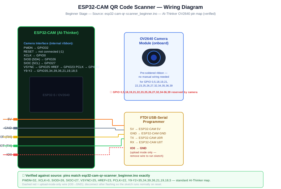
Program the AI-Thinker ESP32-CAM with FTDI TX/RX/GND/5V wiring, ground IO0 only during upload, then remove IO0 from GND before running. The onboard OV2640 camera supplies the frames; Serial Monitor is the first output to verify.
-
1
Unplug USB before changing wires.
-
2
Connect FTDI TX/RX/GND/5V to U0R/U0T/GND/5V (Standard ESP32-CAM flash wiring).
-
3
Connect IO0 to GND (During upload only; remove for run).
-
4
Reconnect USB, upload the sketch, and open Serial Monitor at 115200 baud unless the code says otherwise.
GPIO Mapping
| Signal | ESP32 Pin | Direction | Notes |
|---|---|---|---|
| FTDI TX/RX/GND/5V | U0R/U0T/GND/5V | Ground | Standard ESP32-CAM flash wiring |
| IO0 | GND | Signal | During upload only; remove for run |
Circuit Explanation
The ESP32-CAM uses its onboard OV2640 camera. Programming requires FTDI serial wiring and IO0-to-GND only during upload. A printed QR code or phone screen becomes the target. Good lighting and correct focus matter as much as code.
Engineering Explanation
QR decoding is sensitive to image clarity. Low light, glare, motion blur, high resolution memory pressure, and poor focus can all prevent decoding. A reliable scanner starts with simple Serial output, fixed lighting, and a known QR code before adding actions such as relays or web requests.
Libraries
- Arduino ESP32 coreInstall ESP32 board support in Arduino IDE.
Code
Copy into Arduino IDE. Install any libraries noted in the component guides first.
// ESP32-CAM QR Code Scanner - Beginner
// Library: https://github.com/zbar/zbar or Quirc port for ESP32
// Use: ESP32-CAM-QR library by martinius96
#include "esp_camera.h"
#include <quirc.h>

// AI-Thinker pin map
#define PWDN_GPIO_NUM  32
#define RESET_GPIO_NUM -1
#define XCLK_GPIO_NUM   0
#define SIOD_GPIO_NUM  26
#define SIOC_GPIO_NUM  27
#define Y9_GPIO_NUM    35
#define Y8_GPIO_NUM    34
#define Y7_GPIO_NUM    39
#define Y6_GPIO_NUM    36
#define Y5_GPIO_NUM    21
#define Y4_GPIO_NUM    19
#define Y3_GPIO_NUM    18
#define Y2_GPIO_NUM     5
#define VSYNC_GPIO_NUM 25
#define HREF_GPIO_NUM  23
#define PCLK_GPIO_NUM  22

struct quirc *qr;

void setup() {
  Serial.begin(115200);

  camera_config_t config;
  config.ledc_channel = LEDC_CHANNEL_0;
  config.ledc_timer   = LEDC_TIMER_0;
  config.pin_d0 = Y2_GPIO_NUM; config.pin_d1 = Y3_GPIO_NUM;
  config.pin_d2 = Y4_GPIO_NUM; config.pin_d3 = Y5_GPIO_NUM;
  config.pin_d4 = Y6_GPIO_NUM; config.pin_d5 = Y7_GPIO_NUM;
  config.pin_d6 = Y8_GPIO_NUM; config.pin_d7 = Y9_GPIO_NUM;
  config.pin_xclk  = XCLK_GPIO_NUM; config.pin_pclk  = PCLK_GPIO_NUM;
  config.pin_vsync = VSYNC_GPIO_NUM; config.pin_href  = HREF_GPIO_NUM;
  config.pin_sscb_sda = SIOD_GPIO_NUM; config.pin_sscb_scl = SIOC_GPIO_NUM;
  config.pin_pwdn  = PWDN_GPIO_NUM;  config.pin_reset = RESET_GPIO_NUM;
  config.xclk_freq_hz = 10000000;
  config.pixel_format = PIXFORMAT_GRAYSCALE; // Quirc needs grayscale
  config.frame_size   = FRAMESIZE_QVGA;      // 320x240 for speed
  config.jpeg_quality = 12;
  config.fb_count     = 1;

  if (esp_camera_init(&config) != ESP_OK) {
    Serial.println("Camera init failed"); return;
  }

  qr = quirc_new();
  quirc_resize(qr, 320, 240);
  Serial.println("QR Scanner ready — point at a QR code");
}

void loop() {
  camera_fb_t *fb = esp_camera_fb_get();
  if (!fb) { delay(100); return; }

  uint8_t *qr_buf = quirc_begin(qr, NULL, NULL);
  memcpy(qr_buf, fb->buf, fb->len);
  quirc_end(qr);
  esp_camera_fb_return(fb);

  int count = quirc_count(qr);
  for (int i = 0; i < count; i++) {
    struct quirc_code  code;
    struct quirc_data  data;
    quirc_extract(qr, i, &code);
    if (quirc_decode(&code, &data) == QUIRC_SUCCESS) {
      Serial.print("QR Decoded: ");
      Serial.println((char*)data.payload);
    }
  }
  delay(200);
}
Code Explanation
The sketch selects the AI-Thinker OV2640 pin map, captures QVGA grayscale frames, copies each frame into Quirc's pixel buffer, runs Quirc detection/decoding on the ESP32, and prints successful UTF-8 QR payloads to Serial Monitor. The beginner code does not send frames to a browser, server, API, or cloud decoder.
Expected Output
Serial Monitor prints "QR Scanner ready" after camera and Quirc setup. When a readable QR code is in view, it prints "QR Decoded:" followed by the decoded payload text.
Troubleshooting
- QR code is never decoded Use a larger printed QR code, improve lighting, reduce glare, hold the code square to the camera, and test at 10-20 cm before changing the code.
- Camera init fails Check board selection, camera model, ribbon cable, and power supply.
- Decoded text is inconsistent Hold the code still, avoid glossy screens, and keep the QR code large enough that the finder squares are sharp in the QVGA frame.
- Board resets during scanning Use a stable 5 V supply with enough current.
- Upload works but the sketch will not run Remove the IO0-to-GND jumper after uploading, then reset the ESP32-CAM for normal run mode.
Common Mistakes
- Testing with a tiny QR code too close to the camera.
- Using glossy phone screens with glare.
- Leaving IO0 grounded after upload.
- Running high camera resolution that leaves too little memory for decoding.
- Adding door-lock hardware before QR decoding is reliable.
Testing Checklist
- Verify the AI-Thinker ESP32-CAM upload wiring with GPIO0 grounded only during upload.
- Remove GPIO0 from GND, reset the board, and confirm "QR Scanner ready" appears in Serial Monitor.
- Test one large printed QR code under steady lighting before using phone screens or small labels.
- Confirm the payload prints to Serial before adding web UI, SD logging, MQTT, locks, relays, or buzzers.
- Power-cycle the board and confirm it starts scanning again.
Engineering Tips
- Prove camera capture before QR decoding.
- Use matte printed codes for testing.
- Keep the first decoded action harmless, such as Serial output.
- Do not connect locks or relays until false reads are handled.
- Add a timeout so the same QR code does not trigger repeatedly.
Performance Tips
- Use modest resolution to preserve RAM.
- Decode only when a new frame is ready.
- Avoid unnecessary Wi-Fi while decoding if memory is tight.
- Use simple payload strings in QR codes.
Upgrade Ideas
- Add an OLED display to show decoded QR content without a computer
- Add a buzzer beep on successful decode
- Log decoded URLs to Serial and open them automatically via a companion app
- Add a green LED that lights for 1 second after a successful decode
Real-World Applications
- Inventory label scanner
- Classroom attendance demo
- Prototype access control input
- Museum exhibit information trigger
Downloads
- ESP32-CAM QR Code Scanner Arduino sketchUse the code section as the source sketch.
- Bench test checklistFollow the testing checklist before permanent installation.
FAQs
Why does QR scanning fail in low light?
The decoder needs a sharp, high-contrast camera frame. Improve lighting, reduce glare, and hold the QR code still before changing the code.
What QR code size works best at close range?
Start with a larger printed QR code at about 10-20 cm, matching the troubleshooting guidance, then adjust distance after the scanner decodes reliably.
Why does the ESP32-CAM reset during scanning?
Camera capture can draw enough current to expose a weak 5 V supply. Use the stable supply listed in the project and remove IO0 from GND after uploading.
Review, Testing, and References
Author: Abdul Mubeen and the ESP32 Engine editorial team. Last updated: 2026-08-23. Reviewed: wiring logic, Arduino code structure, beginner safety, and learning sequence.
Educational level: Intermediate. Estimated completion time: 90-130 min. This project is for learning and prototyping; production or unattended hardware needs additional engineering review.
Project Complete!
You completed ESP32-CAM QR Code Scanner as a real ESP32 engineering build, not just a wiring demo. You now know how to test the input, protect the circuit, explain the code, and improve the project safely.
- Read and verify project input hardware
- Map signals to safe ESP32 GPIO pins
- Debug with Serial Monitor
- Apply safety and performance checks
- Plan the next learning step