
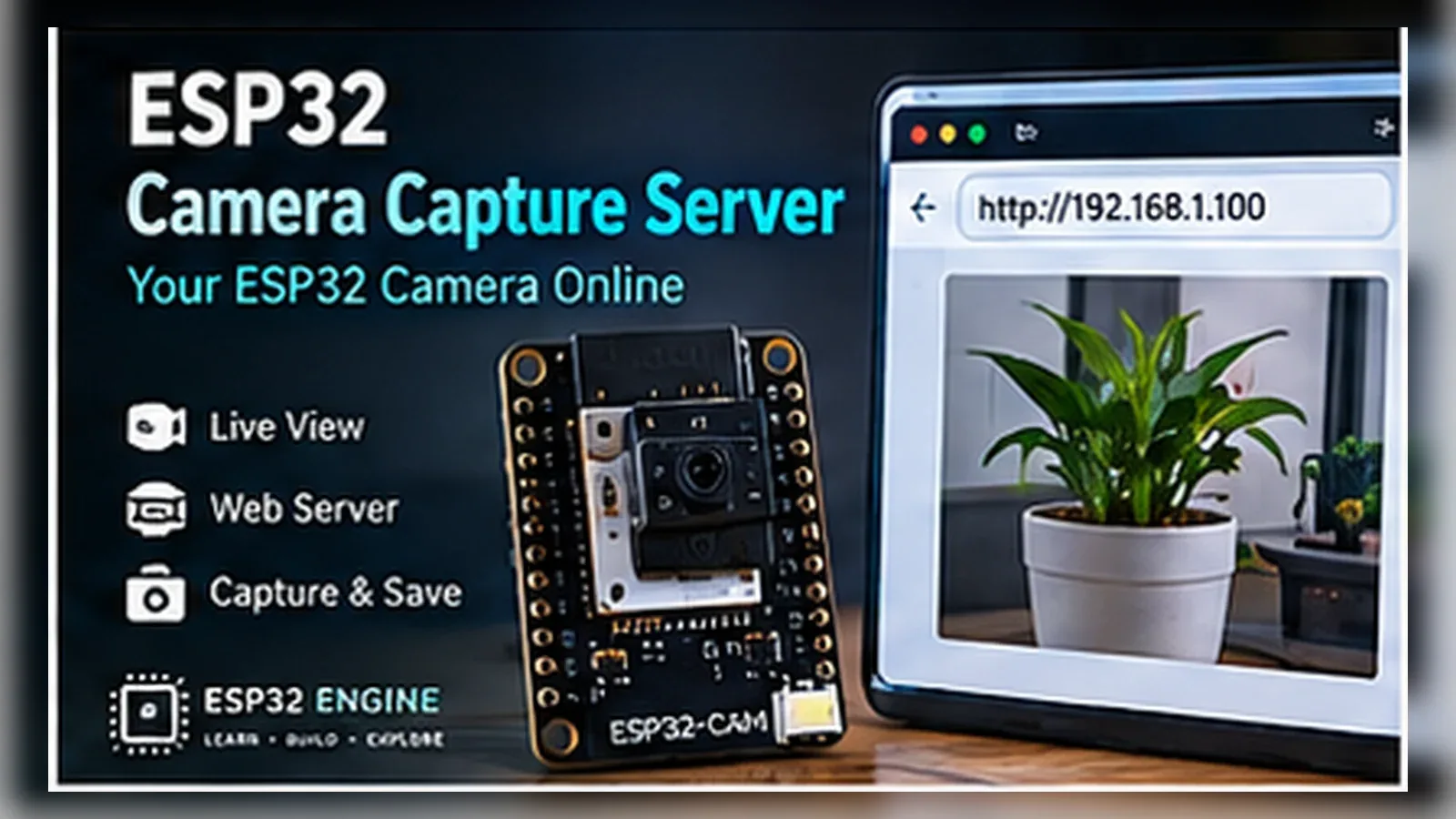
Build a Camera Capture Server
The Story
ESP32 Camera Capture Server solves a real beginner problem: turning an ESP32 reading into a useful physical or networked result. Build this when you are ready to combine camera hardware, Wi-Fi, memory limits, and power stability in one project.
The tutorial focuses on the engineering path: prove the input, understand the circuit, write readable code, then test the output under real conditions.
Explain Like I'm 12
The ESP32-CAM is a tiny digital camera with a web window. The camera captures a frame, the ESP32 compresses or buffers it, and the browser asks for the latest picture.
Safety Standards
- Unplug USB before changing jumper wires. Recheck 3.3 V, 5 V, and GND before reconnecting power.
- Do not power motors, pumps, LED strips, or servos from the ESP32 3.3 V pin. Use a suitable external supply and common ground.
- Breadboards are for low-current prototypes. Move high-current or unattended builds to proper terminals, enclosure, strain relief, and fusing.
What You Will Build
A local ESP32-CAM snapshot server that initializes the AI-Thinker OV2640 camera, joins Wi-Fi, and returns one JPEG image from /capture when a browser requests it.
Learning Objectives
- Program an ESP32-CAM safely with an FTDI adapter.
- Understand boot mode using IO0.
- Capture a camera frame and serve or store it.
- Recognize power-related camera failures.
- Tune resolution and JPEG quality for reliability.
Components List
- ESP32-CAM AI-Thinker board with OV2640ESP32-family camera board; review ESP32 power, boot, GPIO, and Wi-Fi basics while using the fixed AI-Thinker camera pin map here
- FTDI USB-to-serial adapterUse 3.3 V logic; power the ESP32-CAM from a stable 5 V source
- Stable 5 V supply rated for at least 500 mACamera capture plus Wi-Fi can brown out weak supplies
- Jumper wiresProgramming connections and IO0 upload jumper
- USB data cableConnects the FTDI adapter to your computer
Bill of Materials
| Part | Qty | Estimated Cost | Notes |
|---|---|---|---|
| ESP32-CAM AI-Thinker board with OV2640 | 1 | Varies | Required camera board |
| FTDI USB-to-serial adapter | 1 | Varies | 3.3 V logic for programming |
| Stable 5 V supply | 1 | Varies | At least 500 mA; more headroom is better |
| Jumper wires | 1 set | Varies | Programming connections |
Wiring
The ESP32-CAM board already connects the OV2640 camera to the ESP32 internally. The builder only wires the FTDI programmer, 5 V power, common ground, and the IO0-to-GND jumper used for flashing.
-
1
Unplug USB before changing wires.
-
2
Connect FTDI TX to ESP32-CAM U0R / GPIO3.
-
3
Connect FTDI RX to ESP32-CAM U0T / GPIO1.
-
4
Connect FTDI GND to ESP32-CAM GND.
-
5
Connect a stable 5 V supply to ESP32-CAM 5V and GND.
-
6
For upload only, connect IO0 / GPIO0 to GND.
-
7
Upload the sketch, then remove the IO0-to-GND jumper and press reset for normal boot.
GPIO Mapping
| Signal | ESP32 Pin | Direction | Notes |
|---|---|---|---|
| PWDN | GPIO32 | Output | AI-Thinker camera power-down pin. |
| RESET | -1 | Not connected | Not connected on the AI-Thinker module. |
| XCLK | GPIO0 | Output | Camera clock; also the upload-mode boot strap pin. |
| SIOD / SDA | GPIO26 | I/O | Camera configuration bus. |
| SIOC / SCL | GPIO27 | Output | Camera configuration bus. |
| VSYNC | GPIO25 | Input | Frame sync. |
| HREF | GPIO23 | Input | Line sync. |
| PCLK | GPIO22 | Input | Pixel clock. |
| Y9-Y2 | GPIO35, GPIO34, GPIO39, GPIO36, GPIO21, GPIO19, GPIO18, GPIO5 | Input | Parallel pixel data bus. |
| FTDI UART | GPIO3 / GPIO1 | I/O | Programming serial connection. |
| 5 V | 5V | Power | Use a stable supply with camera and Wi-Fi current headroom. |
| GND | GND | Ground | Common ground for FTDI and 5 V supply. |
Circuit Explanation
The ESP32-CAM board already connects the OV2640 camera to the ESP32 internally. Programming usually uses an FTDI adapter. Stable 5 V power is important because camera capture and Wi-Fi transmit peaks can reset weak supplies. IO0 is grounded only for flashing and released for normal boot.
Engineering Explanation
Camera projects are memory and power sensitive. Resolution, JPEG quality, PSRAM availability, Wi-Fi signal, and SD card writes all affect reliability. Start with low resolution, confirm capture works, then increase quality one step at a time.
Libraries
- Arduino ESP32 coreInstall ESP32 board support in Arduino IDE.
Code
Copy into Arduino IDE. Install any libraries noted in the component guides first.
#include "esp_camera.h"
#include <WiFi.h>
#include <WebServer.h>

const char* WIFI_SSID = "YOUR_SSID";
const char* WIFI_PASS = "YOUR_PASSWORD";
WebServer server(80);

#define PWDN_GPIO_NUM 32
#define RESET_GPIO_NUM -1
#define XCLK_GPIO_NUM 0
#define SIOD_GPIO_NUM 26
#define SIOC_GPIO_NUM 27
#define Y9_GPIO_NUM 35
#define Y8_GPIO_NUM 34
#define Y7_GPIO_NUM 39
#define Y6_GPIO_NUM 36
#define Y5_GPIO_NUM 21
#define Y4_GPIO_NUM 19
#define Y3_GPIO_NUM 18
#define Y2_GPIO_NUM 5
#define VSYNC_GPIO_NUM 25
#define HREF_GPIO_NUM 23
#define PCLK_GPIO_NUM 22

void handleCapture() {
  camera_fb_t* fb = esp_camera_fb_get();
  if (!fb) {
    server.send(500, "text/plain", "Camera capture failed");
    return;
  }
  server.send_P(200, "image/jpeg", (const char*)fb->buf, fb->len);
  esp_camera_fb_return(fb);
}

void setupCamera() {
  camera_config_t config;
  config.ledc_channel = LEDC_CHANNEL_0;
  config.ledc_timer = LEDC_TIMER_0;
  config.pin_d0 = Y2_GPIO_NUM;
  config.pin_d1 = Y3_GPIO_NUM;
  config.pin_d2 = Y4_GPIO_NUM;
  config.pin_d3 = Y5_GPIO_NUM;
  config.pin_d4 = Y6_GPIO_NUM;
  config.pin_d5 = Y7_GPIO_NUM;
  config.pin_d6 = Y8_GPIO_NUM;
  config.pin_d7 = Y9_GPIO_NUM;
  config.pin_xclk = XCLK_GPIO_NUM;
  config.pin_pclk = PCLK_GPIO_NUM;
  config.pin_vsync = VSYNC_GPIO_NUM;
  config.pin_href = HREF_GPIO_NUM;
  config.pin_sscb_sda = SIOD_GPIO_NUM;
  config.pin_sscb_scl = SIOC_GPIO_NUM;
  config.pin_pwdn = PWDN_GPIO_NUM;
  config.pin_reset = RESET_GPIO_NUM;
  config.xclk_freq_hz = 20000000;
  config.pixel_format = PIXFORMAT_JPEG;
  config.frame_size = FRAMESIZE_QVGA;
  config.jpeg_quality = 12;
  config.fb_count = 1;

  esp_err_t err = esp_camera_init(&config);
  if (err != ESP_OK) {
    Serial.printf("Camera init failed: 0x%x\n", err);
    while (true) delay(1000);
  }
}

void setup() {
  Serial.begin(115200);
  setupCamera();
  WiFi.begin(WIFI_SSID, WIFI_PASS);
  while (WiFi.status() != WL_CONNECTED) delay(300);
  server.on("/capture", HTTP_GET, handleCapture);
  server.begin();
  Serial.print("Open http://");
  Serial.print(WiFi.localIP());
  Serial.println("/capture");
}

void loop() {
  server.handleClient();
}
Code Explanation
The sketch fills camera_config_t with the AI-Thinker OV2640 pin map, starts QVGA JPEG capture, connects to Wi-Fi, registers /capture, and returns each frame buffer as image/jpeg before releasing it with esp_camera_fb_return().
Expected Output
Serial Monitor should print the ESP32-CAM IP address. Opening /capture in a browser on the same network should return a JPEG snapshot from the OV2640 camera.
Build Photos
- Breadboard overviewShow ESP32, module, output device, and power rails.
- Close-up wiringShow signal pins clearly enough for learners to compare.
- Working outputShow Serial Monitor, LEDs, display, or dashboard after the condition changes.
Troubleshooting
- Camera init failed Check camera model, ribbon cable seating, and use a stable 5 V supply.
- Brownout reset appears Use a better 5 V supply and shorter power wires.
- Web page loads but image is blank Lower resolution and confirm PSRAM availability.
- Upload works but board will not run Remove IO0 from GND and press reset after flashing.
Common Mistakes
- Leaving IO0 connected to GND after upload.
- Powering ESP32-CAM from a weak USB serial adapter.
- Selecting the wrong camera model in code.
- Using high resolution before confirming basic capture.
- Touching the camera ribbon cable while powered.
Testing Checklist
- Upload a simple Blink sketch first to confirm the board and USB cable work.
- Wire only power and ground, then confirm the board still boots.
- Upload with IO0 connected to GND, then remove the jumper for normal boot.
- Confirm Serial Monitor prints the local IP address.
- Open the /capture URL and verify a JPEG image appears.
- Power-cycle the project and confirm it starts in a safe state.
Engineering Tips
- Start with the official CameraWebServer example.
- Use 5 V power with enough current headroom.
- Avoid high frame rate expectations; ESP32-CAM is not a full CCTV system.
- Keep camera ribbon cable fully seated and locked.
- Test on a local network before exposing anything outside your LAN.
Performance Tips
- Use lower resolution for faster capture.
- Reduce JPEG quality number carefully; smaller files use less network time.
- Store images only when motion or a timer requires it.
- Keep Wi-Fi signal strong to reduce failed transfers.
Upgrade Ideas
- Publish readings to an MQTT broker or Home Assistant
- Add timed image capture for timelapse.
Real-World Applications
- Timelapse camera
- Workshop inspection camera
- Plant growth image logger
- Simple local monitoring camera
Downloads
- ESP32 Camera Capture Server Arduino sketchUse the code section as the source sketch.
- Bench test checklistFollow the testing checklist before permanent installation.
FAQs
Why does the ESP32-CAM show a brownout reset?
Camera capture plus Wi-Fi can exceed what a weak USB serial adapter can supply. Power the board from a stable 5 V source and keep the power wires short.
Can I expose the camera server to the public internet?
Keep this tutorial on a trusted local network. Do not publish the camera URL publicly unless you add proper authentication, network isolation, and consent from anyone who may be recorded.
Why does upload work but the camera sketch will not run?
IO0 must be connected to GND only during flashing. Remove the IO0 jumper after upload and press reset so the ESP32-CAM boots the sketch.
Review, Testing, and References
Author: Abdul Mubeen and the ESP32 Engine editorial team. Last updated: 2026-08-26. Reviewed: wiring logic, Arduino code structure, beginner safety, and learning sequence.
Educational level: Intermediate. Estimated completion time: 90-120 min. This project is for learning and prototyping; production or unattended hardware needs additional engineering review.
Project Complete!
You completed ESP32 Camera Capture Server as a real ESP32-CAM snapshot build. You now know how to upload with GPIO0, power the camera board, serve /capture locally, and troubleshoot camera initialization.
- Read and verify project input hardware
- Map signals to safe ESP32 GPIO pins
- Debug with Serial Monitor
- Apply safety and performance checks
- Plan the next learning step